Quantcast
Channel: Testing and Commissioning - Technical Articles | EEP - Electrical Engineering Portal
Viewing all 158 articles
Browse latest View live

Field Inspection and Testing of Medium-Voltage Motor Control Centres (MCCs)

$
0
0
Field Inspection and Testing of Medium-Voltage Motor Control Centres - MCCs

Field Inspection and Testing of Medium-Voltage Motor Control Centres - MCCs (Photo by Arrow Speed Controls; arrowspeed.com // MX3 Medium Voltage Solid State Soft-Starter)

Equipment and Installation Check Items

  1. Check MCC equipment for: alignment, levelness, and tightness of all bolting.
  2. Check all equipment for: removal of blocking, supports, temporary ties, and temporary wire jumpers.
  3. Check that all protective barriers are properly installed.
  4. Check door alignment of individual starter units and door interlock operation.
  5. Check operation of external overload protective device reset.
  6. Check that drawout contacts are completely disconnected when drawout handle is operated.
  7. Check CPT and PT fuses for: size, type, and circuit location.
  8. Check PT and CT ratios.
  9. Check CPT size and rating.
  10. Check voltage rating of contactor coil.
  11. Verify that metering or relaying devices using resistance temperature detectors (RTDs) have the correct rating.
  12. Check fuses and wiring to power factor correction capacitors for size and rating.
  13. Check all components for proper identification according to the drawings and specifications.

Equipment and Installation Inspection Items

  1. Inspect MCC bus bar connections for tightness by verifying that the torque meets manufacturer’s specifications. Verify that connection hardware is consistent with the Owner’s project specifications.
  2. Inspect MCC bus bar supports for: cleanliness and tightness.
  3. Inspect ground connections to ground bus.
  4. Inspect operation of: mechanical interlocks, position indicators, drawout or rollout mechanism, and all safety interlock features.
  5. Inspect contactor rating.
  6. Inspect contactor-insulating parts for: cleanliness and dryness.
  7. Inspect contactor electrical contact surfaces for cleanliness and smoothness. Lubricate per manufacturer’s instructions.
  8. Inspect contactor-seating surfaces of unplated and laminated magnet faces of contactor and relays. Remove any rust or rust preventative if present.
  9. Inspect contactor power stabs and adjust per manufacturer’s instructions.
  10. Inspect manual operation of contactor and mechanical relay devices to verify that all parts are free and that they work smoothly. For air contactors, verify adjustment for contact wipe and alignment per manufacturer’s instructions.
  11. Inspect lubrication of contactor moving parts.
  12. Inspect contactor vacuum bottles for damage.
  13. Inspect size, type, and rating of current-limiting power fuses.
  14. Inspect overload protective device rating and setting.

Testing Requirements

  1. Test insulation resistance of MCC bus with a 1-minute test (phase to phase and phase to ground).
  2. Test insulation resistance of control power and instrument transformers with a 1-minute test at applicable voltage.
  3. Test insulation resistance of contactor (closed position) with a 1-minute test (phase to phase and phase to ground).
  4. Test contactor contact resistance with micro-ohmmeter.
  5. Test integrity of each vacuum interrupter on a vacuum contactor in accordance with manufacturer’s instructions.
  6. Calibrate and test each protective relay with settings on devices being in accordance with approved relay settings summary or coordination study.
  7. Test contactor drop-out time if power disturbance ride-through is specified.
  8. Test operation of all space heaters including switching and indicating devices.
  9. Test CT circuit by applying current to the CT primary circuit and verifying operation of all applicable relays and metering devices.
    When primary current injection is not practicable because of size of current requirements, test CT secondary circuit by applying current to CT secondary circuit with CT disconnected, and verify operation of all applicable relays and metering devices.
    Test window-type ground CTs and their circuits by applying current to a conductor passed through the window.
  10. When specified on the Data Sheet, perform a CT ratio-verification test using the voltage or current method in accordance with ANSI C57.13.1.
  11. Test voltmeter, ammeter, and related selector switches when installed.
  12. Test proper operation of overload protective device. Operate mechanical trip option if present.

Function Test Items

  1. Function-test each contactor in the test position:
    1. Close and trip contactor with all local and remote control devices. Verify operation of all auxiliary devices by functional testing.
    2. Trip contactor from each protective device individually. Verify operation of all auxiliary devices.
  2. Verify operation of capacitor discharge resistor system on power factor capacitors using a properly sized voltmeter.

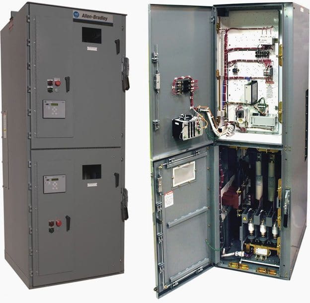
Example of MV MCC Switchgear

Allen-Bradley CENTERLINE Medium Voltage Motor Control Center

Allen-Bradley CENTERLINE Medium Voltage Motor Control Center


Reference: Field Inspection and Testing of New Electrical Equipment – Process Industry Practices (PIP), Construction Industry Institute

Power Transformer Turns Ratio Test

$
0
0
Power Transformer Turns Ratio Test

Power Transformer Turns Ratio Test

Turns ratio between the windings

The turns ratio test is an AC low voltage test which determines the ratio of the high voltage winding to all other windings at no-load. The turns ratio test is performed on all taps of every winding.

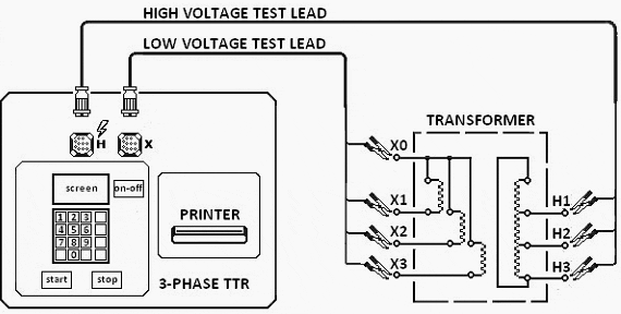
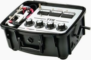
The Transformer Turns Ratio tester (TTR) is device used to measure the turns ratio between the windings (example shown below).

Voltage is applied on the H marked leads and measured of the X marked lead by the test set.

Ratio measurements are conducted on all tap positions and calculated by dividing the induced voltage reading into the applied voltage value. When ratio tests are being made on three-phase transformers, the ratio is taken on one phase at a time with a three-phase TTR until the ratio measurements of all three phases are completed.

Figure 1 - Three-phase Transformer Turns Rati (TTR) Connection diagram.

Figure 1 – Three-phase Transformer Turns Rati (TTR) Connection diagram.


Measured ratio variations should be within 0.5% of the nameplate markings.

Some TTR can perform transformer ratio measurement and also assess if on-load tap changer contacts are making satisfactorily during its transition from one tap position to the next position.

Example of single phase, hand-cranked TTR - Transformer Turns Ratio Test Set

Example of single phase, hand-cranked TTR – Transformer Turns Ratio Test Set (Measures the turns ratio and exciting current of windings in power, potential and current transformers.)

Turns Ratio Test Procedure, Step by Step

Step 1.

Isolate the equipment, apply working grounds to all incoming and outgoing cables and disconnect all incoming and outgoing cables from the transformer bushing terminals connections.

Disconnected cables should have sufficient clearance from the switchgear terminals greater that the phase spacing distance. Use nylon rope to hold cable away from incoming and outgoing terminals as required.


Step 2.

Connect the H designated three-phase test lead with the military style connector at one end to the mating connection on the test set marked with an H. Ensure that the connector’s index notch lines up properly.


Step 3.

Connect the X designated three-phase test of lead military style connector at one end to the mating connection on the test set marked with an X. Ensure that the connector’s index notch lines up properly.


Step 4.

Connect the H1, H2, H3 designated test lead to the corresponding H1, H2, H3 transformer terminal / bushing. Connect the H0 test lead if H0 terminal/bushing is present.

Refer to Figure 1.


Step 5.

Connect the X1, X2, X3 designated test leads to the corresponding X1, X2,X3 transformer terminals / bushings. Connect the X0 test lead if X0 terminal/bushing is present.


Step 6.

Perform turns ratio measurements for all tap positions.


Step 7.

Confirm that the measured ratios is within 0.5% of the calculated ratios.

Important Note:

Transformers that have wye connections but do not have the neutral of the wye brought out shall be tested for ratio with three-phase power supply.

Any inequality in the magnetizing characteristics of the three phases will then result in a shift of the neutral and thereby cause unequal phase voltages. When such inequality is found, the connection should be changed, either to a delta or to a wye connection, and the line voltages measured.

When these are found to be equal to each other and the proper values (1.732 times the phase voltages when connected in wye), the ratio is correct.


Power Transformer Testing – Automatically measuring ratio and winding resistance of all taps/phases

Cant see this video? Click here to watch it on Youtube.

Reference: Substation Commissioning Course – Raymond Lee, Technical Trainer

Power Transformer Capacitance and Dissipation Factor Test

$
0
0
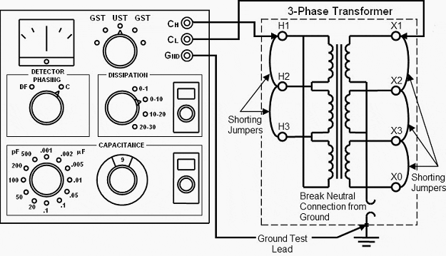
Figure 1 - Capacitance and Dissipation Factor Test connection diagram

Figure 1 – Capacitance and Dissipation Factor Test connection diagram

Transformer insulation system

The capacitance and dissipation factor test is an AC low voltage maintenance test and is very similar to the power factor test.

The test as it is termed, measures the capacitance and dissipation factor (or loss factor) of the transformer insulation system. This test may be required to be performed during the acceptance testing stage to establish a baseline reading for future test comparison.

While the transformer preparation is identical to the power factor test procedure, there is no requiremnts to make connection changes once the initial test set connections are made. High-voltage winding and low-voltage winding test set connection changes are made through a selector switch provided on the test set.

Winding capacitance and dissipation factor test values are obtained by balancing a null meter for each variable at every the measured variable selector switch positions.

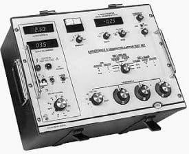
Capacitance and Dissipation Factor Test Set

MEGGER Semi-Automatic Capacitance and Dissipation Factor Test Set (Direct readout of capacitance, dissipation factor and watts dissipated)

Capacitance and Dissipation Factor Test Procedure

(Two winding dry-type transformer)

Step 1.

Isolate the equipment, apply working grounds to all incoming and outgoing cables and disconnect all incoming and outgoing cables from the transformer bushing terminals. Disconnected cables should have sufficient clearance from the switchgear terminals greater that the phase spacing distance.

Use nylon rope to hold cable away from incoming and outgoing terminals as required.

Step 2.

Isolate the neutral bushing connection if applicable from the transformer grounding bar.

Step 3.

Short-circuit all high voltage bushing terminals together.

Step 4.

Short-circuit all low voltage bushing terminals and the neutral bushing terminal together.

Step 5.

Connect the capacitance and dissipation factor test set. Refer to Figure 1 above.

Step 6.

Record the capacitance and dissipation factor values once the null meter is balance for both phasing position. Record values for the five test-variable selector switch position.


Power Transformer Testing – Measuring capacitance and power factor or dissipation factor

The condition of the bushings and the overall insulation of power transformers can be investigated by measuring the capacitance and dissipation factor, also known as the tangent delta, or power factor. Aging and decomposition of the insulation, or the ingress of water, increases the losses and thus more energy is turned into heat in the insulation.

The level of this dissipation is expressed by the dissipation factor or power factor.

Cant see this video? Click here to watch it on Youtube.

Reference: Substation Commissioning Course – Raymond Lee, Technical Trainer

Inspection and test procedures for Rotating Machinery, Synchronous Motors and Generators

$
0
0
Inspection and test procedures of Rotating Machinery, Synchronous Motors and Generators

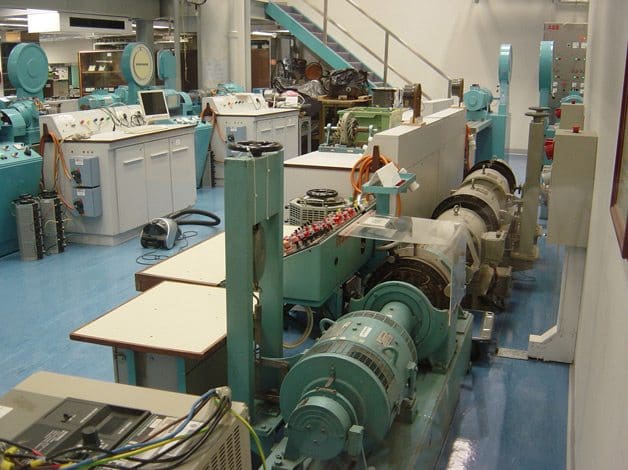
Inspection and test procedures of Rotating Machinery, Synchronous Motors and Generators (On photo: Small machine test set – ee.polyu.edu.hk)

Procedures (Index)

  1. Visual and Mechanical Inspection
  2. Electrical Tests
  3. Test Values
    1. Visual and Mechanical Tests
    2. Electrical Tests
  4. Pictures:
    1. Electrical machine wired for electrical testing
    2. The Electrical Machines Laboratory
  5. TABLE 100.10 – Maximum Allowable Vibration Amplitude
  6. TABLE 100.12 – US Standard Fasteners

1. Visual and Mechanical Inspection

  1. Compare equipment nameplate datawith drawings and specifications.
  2. Inspect physical and mechanical condition.
  3. Inspect anchorage, alignment, and grounding.
  4. Inspect air baffles, filter media, cooling fans, slip rings, brushes, and brush rigging.
  5. Inspect bolted electrical connections for high resistance using one or more of the following?methods:
    1. Use of low-resistance ohmmeter?in accordance with procedure for LR ohmmeter?usage.
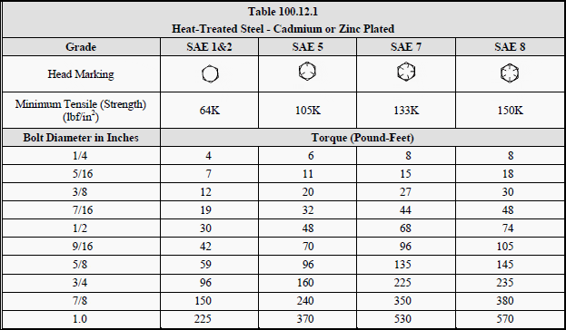
    2. Verify tightness of accessible bolted electrical connections by calibrated torque-wrench?method in accordance with manufacturer?s published data or Table 100.12?(see below).
    3. Perform thermographic survey.
  6. Perform special tests such as air-gap spacing and machine alignment.
  7. Verify the application of appropriatelubrication and lubrication systems.
  8. Verify that resistance temperature detector (RTD) circuits conform to drawings.

Go to Index ↑


2. Electrical Tests

  1. Perform resistance measurements through bolted connections with a low-resistance ohmmeter,?if applicable.
  2. Perform insulation-resistance tests inaccordance with ANSI/IEEE Standard 43.
    1. Machines larger than 200 horsepower (150 kilowatts):
      Test duration shall be for ten minutes. Calculate polarization index.
    2. Machines 200 horsepower (150 kilowatts) and less:
      Test duration shall be for one minute. Calculate dielectric-absorption ratio.
  3. Perform dc dielectric withstand voltage tests on machines rated at 2300 volts and greater in?accordance with ANSI/IEEE Standard 95.
  4. Perform phase-to-phase stator resistance test on machines 2300 volts and greater.
  5. ** Perform insulation power-factoror dissipation-factor tests.
  6. ** Perform power-factor tip-up tests.
  7. ** Perform surge comparison tests.
  8. Perform insulation-resistance test on insulated bearings in accordance with manufacturer?s?published data, if applicable.
  9. Test surge protection devices.
  10. Test motor starter.
  11. Perform resistance tests on resistance temperature detector (RTD) circuits.
  12. Verify operation of machine space heater, if applicable.
  13. ** Perform vibration test.
  14. Perform insulation-resistance tests on the main rotating field winding, the exciter-field winding, and the exciter-armature winding in accordance with ANSI/IEEE Standard 43.
  15. ** Perform an ac voltage-drop test on all rotating field poles.
  16. ** Perform a high-potential test on the excitation system in accordance with ANSI/IEEE Standard?421.3.
  17. Measure resistance of machine-field winding, exciter-stator winding, exciter-rotor windings,?and field discharge resistors.
  18. ** Perform front-to-back resistance tests on diodes and gating tests of silicon-controlled rectifiers?for field application semiconductors.
  19. Prior to re-energizing, apply voltage to the exciter supply and adjust exciter-field current to?nameplate value.
  20. Verify that the field application timer and the enable timer for the power-factor relay have been?tested and set to the motor drive manufacturer?s recommended values.
  21. ** Record stator current, stator voltage, and field current for the complete acceleration period?including stabilization time for a normally loaded starting condition. From the recording?determine the following information:
    1. Bus voltage prior to start.
    2. Voltage drop at start.
    3. Bus voltage at machine full-load.
    4. Locked-rotor current.
    5. Current after synchronization but before loading.
    6. Current at maximum loading.
    7. Acceleration time to near synchronous speed.
    8. Revolutions per minute (RPM) just prior to synchronization.
    9. Field application time.
    10. Time to reach stable synchronous operation.
  22. ** Plot a V-curve of stator current versus excitation current at approximately 50 percent load to?check correct exciter operation.
  23. ** If the range of exciter adjustment and machine loading permit,reduce excitation to cause power?factor to fall below the trip value of the power-factor relay. Verify relay operation.

** OPTIONAL

Go to Index??


3. Test Values

3.1 Visual and Mechanical Test Values

  1. Inspection:
    1. Air baffles shall be clean and installed in accordance with manufacturer?s published?data.
    2. Filter media shall be clean and installed in accordance with manufacturer?s published?data.
    3. Cooling fans shall operate.
    4. Slip ring alignment shall be within manufacturer?s published tolerances.
    5. Brush alignment shall be within manufacturer?s published tolerances.
    6. Brush rigging shall be in accordance with manufacturer?s published data.
  2. Compare bolted connection resistance values to values of similar connections. Investigate any?values that deviate from similar bolted connections by more than 50 percent of the lowest?value.
  3. Bolt-torque levels should be in accordance with manufacturer?s published data. In the absence?of manufacturer?s published data, use Table 100.12 (see below)
  4. Results of thermographic survey to be analysed.
  5. Air-gap spacing and machine alignment shall be in accordance with manufacturer?s published?data.

Go to Index??


3.2 Electrical Test Values

  1. Compare bolted connection resistance values tovalues of similar connections. Investigate any?values that deviate from similar bolted connections by more than 50 percent of the lowest?value.
  2. The dielectric absorption ratio or polarization index shall not be less than 1.0. The?recommended minimum insulation resistance (IR 1 min) test results in megaohms shall be?corrected to 40? C and read as follows:
    1. IR 1 min = kV + 1 for most windings made before 1970 (kV is the rated machine terminal-to-terminal voltage in rms kV)
    2. IR 1 min = 100 megohms for most dc armatureand ac windings built after 1970 (form-wound coils).
    3. IR 1 min = 5 megohms for most machines and random-wound stator coils and form-wound coils rated below 1 kV.
      -
      NOTE: Dielectric withstand voltage and surge comparison tests shall not be performed?on machines having values lower than those indicated above.
  3. If no evidence of distress or insulation failure is observed by the end of the total time of voltage?application during the dielectric withstand test, the test specimen is considered to have passed?the test.
  4. Investigate phase-to-phase stator resistance values that deviate by more than five percent.
  5. Power-factor or dissipation-factor values shall be compared to manufacturer?s published data.?In the absence of manufacturer?s published data these values will be compared with previous?values of similar machines.
  6. Tip-up values shall indicate no significant increase in power factor.
  7. If no evidence of distress, insulation failure, orlack of waveform nesting is observed by the end?of the total time of voltage application during the surge comparison test, the test specimen is?considered to have passed the test.
  8. Insulation resistance of bearings shall be within manufacturer?s published tolerances. In the?absence of manufacturer?s published tolerances, the comparison shall be made to similar?machines.
  9. Test results of surge protection devices shall be in accordance with procedures for testing of LV surge arresters.
  10. Test results of motor starter equipment shall be in accordance with?procedures for testing of motor starter equipment.
  11. RTD circuits shall be in accordance with system design intent and machine protection device?manufacturer?s published data.
  12. Heaters shall be operational.
  13. Vibration amplitudes of the uncoupled and unloaded machine shall not exceed values shown in?Table 100.10 (see below). If values exceed, perform complete vibration analysis.
  14. The recommended minimum insulation resistance (IR1 min) test results in megaohms shall be?corrected to 40? C and read as follows:
    1. IR 1 min= kV + 1 for most windings made before 1970, all field windings (kV is the rated machine terminal-to-terminal voltage in rms kV)
    2. IR 1 min= 100 megohms for most dc armature and ac windings built after 1970 (form-wound coils).
    3. IR 1 min= 5 megohms for most machines and random-wound stator coils and form-wound coils rated below 1 kV.
      -
      NOTE: Dielectric withstand voltage, high-potential, and surge comparison tests shall?not be performed on machines having values lower than those indicated above.
  15. The pole-pole AC voltage drop shall not exceed 10 percent variance between poles.
  16. If no evidence of distress or insulation failure is observed by the end of the total time of voltage?application during the dielectricwithstand test, the winding is considered to have passed the?test.
  17. The measured resistance values of motor-field windings, exciter-stator windings, exciter-rotor?windings, and field-discharge resistors shall be compared to manufacturer?s published data. In?the absence of manufacturer?spublished data, the comparison shall be made to similar?machines.
  18. Resistance test results of diodes and gating tests of silicon-controlled rectifiers shall be in?accordance with industry standards and system design requirements.
  19. Exciter power supply shall allow exciter-field current to be adjusted to nameplate value.
  20. Application timer and enable timer for power-factor relay test results shall comply with?manufacturer?s recommended values.
  21. Recorded values shall be in accordance with system design requirements.
  22. Plotted V-curve shall indicate correct exciter operation.
  23. When reduced excitation falls below trip value for the power-factorrelay, the relay shall?operate.

Go to Index ↑


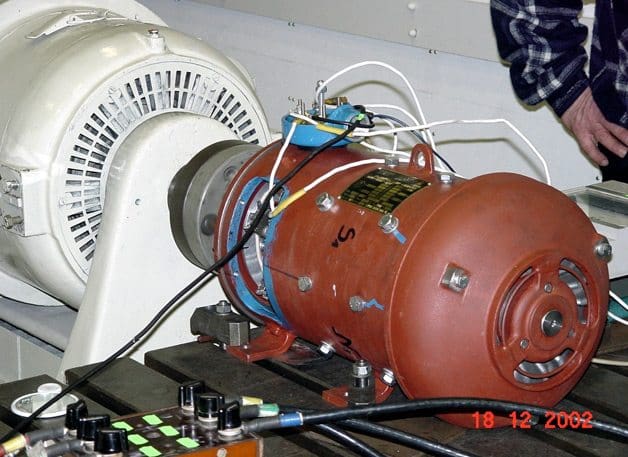
Electrical machine wired for electrical testing

Electrical machine wired for electrical testing (photo credit: komel.katowice.pl)

Electrical machine wired for electrical testing (photo credit: komel.katowice.pl)


Go to Index ↑


The Electrical Machines Laboratory

The Electrical Machines Laboratory (photo credit: ee.polyu.edu.hk)

The Electrical Machines Laboratory (photo credit: ee.polyu.edu.hk)


Go to Index ↑


TABLE 100.10

Maximum Allowable Vibration Amplitude

Table 100.10 - Maximum Allowable Vibration Amplitude

Table 100.10 – Maximum Allowable Vibration Amplitude


Go to Index ↑


TABLE 100.12

US Standard Fasteners – Bolt-Torque Values for Electrical Connections

Table 100.12.1 - Heat-Treated Steel - Cadmium or Zinc Plated

Table 100.12.1 – Heat-Treated Steel – Cadmium or Zinc Plated


Table 100.12.2 - Silicon Bronze Fasteners

Table 100.12.2 – Silicon Bronze Fasteners


Table 100.12.3 - Aluminum Alloy Fasteners

Table 100.12.3 – Aluminum Alloy Fasteners


Table 100.12.4 - Stainless Steel Fasteners

Table 100.12.4 – Stainless Steel Fasteners


a. Consult manufacturer for equipment supplied with metric fasteners.
b. This table is based on bronze alloy bolts having a minimum tensile strength of 70,000 pounds per square inch.
c. This table is based on aluminum alloy bolts having a minimum tensile strength of 55,000 pounds per square inch.
d. This table is to be used for the following hardware types:

  • Bolts, cap screws, nuts, flat washers, locknuts (18?8 alloy)
  • Belleville washers (302 alloy).

Go to Index ↑


Reference:?ANSI/NETA Standard for Acceptance Testing Specifications for Electrical Power Equipment and Systems

Testing Procedures for HV Voltage Transformers

$
0
0
Testing Procedures for HV Voltage Transformers (photo credit: hvcafrica.com)

Testing Procedures for HV Voltage Transformers (photo credit: hvcafrica.com)

Content:

  1. Equipment required for testing
  2. General inspection
  3. Insulation Resistance Test
  4. Polarity Test
  5. Transformer Turns ratio test

1. Equipment required

Following equipment is necessary to perform testings:

  • Polarity test kit
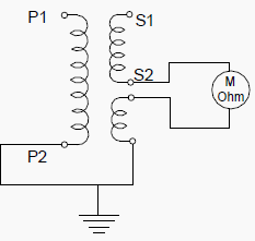
  • Megger 500-5000V
  • Ohmmeter
  • Multimeter
  • Autotransformers & Step-up transformers

Go up to the Content


2. General inspection

Mechanical checks

  • General visual inspection and compliance with the drawings and manuals.
  • Check nameplate ratings and HV, LV terminal markings.
  • Check that all parts of the transformer are properly assembled and tight.
  • Check the HV connections are tight.
  • Check the cable connections on the LV side and the markings.
  • Check the oil levels and inspect for leakage. (Where applicable)

Capacitor dividers type

Check that all parts of the transformers are properly assembled.


Electromagnetic type

Check the installation of different sections.

Electrical Checks

  • Check the equipment grounding (Continuity and connection)
  • Check the fuse rating of secondary side.
  • Perform the operation described in the following

Go up to the Content


Insulation Resistance Test

To obtain values as close as possible to the manufacturer’s specifications the insulators must be very clean. Select the megger range corresponding to the ratings of the equipment under test.

For Primary side, apply voltage depending on rating of voltage rating of VT.

  • For 6.6 kV VT (example), apply 2.5 kV and
  • For 132 kV VT (example), apply 5.0 kV.
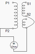
Figure - Measurement between primary and secondary

Figure – Measurement between primary and secondary


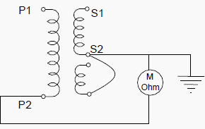
Figure - Measurement between primary and ground

Figure – Measurement between primary and ground


Figure - Measurement between secondaries and between secondary and ground

Figure – Measurement between secondaries and between secondary and ground


Go up to the Content


Polarity Test

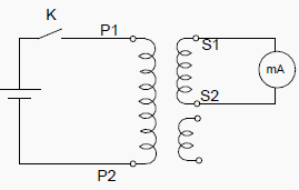
The polarity is checked using the flick method (application of direct current) and check of deflection on a bi-directional milliammeter. The test is also used to check primary and secondary circuit continuity.

  • When switch k is closed, the milliammeter pointer deflects positive.
  • When the circuit is opened, the milliammeter pointer deflects in the negative direction.
Figure - VT Polarity test

Figure – VT Polarity test


Go up to the Content


Transformer Turns ratio test

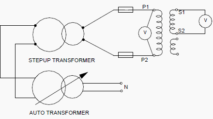
A variable AC source is applied on the primary side. The primary and secondary voltages are measured to determine the ratio V2/V1

Figure - Transformer Turns ratio test

Figure – Transformer Turns ratio test


Go up to the Content


132kv Substation

Go up to the Content

Reference: Contract specific procedure for testing of electrical equipment and 132kV OHL

Testing of power transformer – Measurement of impedance voltage and load loss

$
0
0
Figure 4.1 - Circuit for the impedance and load-loss measurement

Figure 4.1 – Circuit for the impedance and load-loss measurement

Purpose of the measurement

The measurement is carried out to determine the load-losses of the transformer and the impedanse voltage at rated frequency and rated current.

The measurements are made separetely for each winding pair (e.g., the pairs 1-2, 1-3 and 2-3 for a three-winding transformer), and furthermore on the principal and extreme tappings.

Apparatus and measuring circuit

On Figure 1 above (Circuit for the impedance and load-loss measurement) there are following figures:

  • G1 – Supply generator
  • T1 – Step-up transformer
  • T2 – Transformer to be tested
  • T3 – Current transformers
  • T4 – Voltage transformers
  • P1 – Wattmeters
  • P2 – Ammeters (r.m.s. value)
  • P3 – Voltmeters (r.m.s. value)
  • C1 – Capacitor bank

The supply and measuring facilities are not described here. Current is generally supplied to the h.v. winding and the l.v. winding is short-circuited.


Performance of the measurement

If the reactive power supplied by the generator G1 is not sufficient when measuring large transformers, a capacitor bank C1 is used to compensate part of the inductive reactive power taken by the transformer T2.The voltage of the supply generator is raised until the current has attained the required value (25…100 % of the rated current according to the standard 4.1).

In order to increase the accuracy of readings will be taken at several current values near the required level. If a winding in the pair to be measured is equipped with an off-circuit or on-load tap-changer. the measurements are carried out on the principal and extreme tappings.

The readings have to be taken as quickly as possible, because the windings tend to warm up due to the current and the loss values obtained in the measurement are accondingly too high.

It the transformer has more than two windings all winding pairs are measured separately.


Results

Corrections caused by the instrument transformers are made to the measured current, voltage and power values. The power value correction caused by the phase displacement is calculated as follows:

Equation 4.1 - Power value correction formula

Equation 4.1


Where:

  • Pc = corrected power
  • Pe = power read from the meters
  • δu = phase displacement of the voltage transformer in minutes
  • δi = phase displacement of the current transformer in minutes
  • ϕ = phase angle between current and voltage in the measurement (ϕ is positive at inductive load)
  • K = correction

The correction K obtained from equation 4.1 is shown as a set of curves in Figure 4.2.

The corrections caused by the instrument transformers are made separately for each phase, because different phases may have different power factors and the phase displacements of the instrument transformers are generally different.

If the measuring current Im deviates from the rated current IN, the power Pkm and the voltage Ukm at rated current are obtained by applying corrections to the values Pc and Uc relating to the measuring current.

The corrections are made as follows:

Equation 4.2 - Power Pkma

Equation 4.2


Equation 4.3 - Voltage Ukm

Equation 4.3


The correction caused by the phase displacement of instrument transformers (Figure 2):

Figure 4.2 - Phase displacement of istrument transformers

Figure 4.2 – Phase displacement of istrument transformers


Where:

  • K – correction in percent,
  • δu – δi – phase displacement in minutes
  • cosδ – power factor of the measurement.

The sign of K is the same as that of δu – δi.

Mean values are calculated of the values corrected to the rated current and the mean values are used in the following. According to the standards the measured value of the losses shall be corrected to a winding temperature of 75° C (80° C, if the oil circulation is forced and directed).

The transformer is at ambient temperature when the measurements are carried out. and the loss values are corrected to the reference temperature 75° C according to the standards as follows.

The d.c. losses POm at the measuring temperature ϑm are calculated using the resistance values R1m and R2m obtained in the resistance measurement (for windings 1 and 2 between line terminals):

Equation 4.4 - DC Losses

Equation 4.4


The additional losses Pamat the measuring temperature are:

Equation 4.5 - Additional losses

Equation 4.5


Here Pkm is the measured power, to which the corrections caused by the instrument transformer have been made, and which is corrected to the rated current according to equation (4.2).

The short-circuit impedance Zkm and resistance Rkm at the measureing temperature are:

Equation 4.6 - Short-circuit impedance

Equation 4.6


Equation 4.7 - Resistance Rkm

Equation 4.7


  • Ukm is the measured short-circuit voltage corrected according to Equation (4.3);
  • UN is the rated voltage and
  • SN is the rated power.

The short circuit reactance Xk does not depend on the losses and Xk is the same at the measuring temperature (ϑm) and the reference temperature (75 °C), hence:

Equation 4.8

Equation 4.8


When the losses are corrected to 75° C, it is assumed that d.c. losses vary directly with resistance and the additional losses inversely with resistance. The losses corrected to 75° C are obtained as follows:

Equation 4.9

Equation 4.9


Where:

ϑs = 235° C for Copper
ϑs = 225° C for Aluminium

Now the short circuit resistance Rkc and the short circuit impedance Zkc at the reference temperature can be determined:

Equation 4.10

Equation 4.10


Equation 4.11

Equation 4.11


Results

The report indicates for each winding pair the power SN and the following values corrected to 75° C and relating to the principal and extreme tappings.

  • D.C. losses POc (PDC)
  • Additional losses Pac (PA)
  • Load losses Pkc (PK)
  • Short circuit resistance Rkc (RK)
  • Short circuit reaactance Xkc (XK)
  • Short circuit impedance Zkc (ZK)

Reference: Testing of power transformers – ABB

Inspection and Test procedures for Instrument Transformers

$
0
0
Inspection and Test procedures for Instrument Transformers

Inspection and Test procedures for Instrument Transformers (on photo: Ritz Instrument Transformers)

Procedures to follow:

  1. Visual and Mechanical Inspection
  2. Electrical Tests:
    1. Electrical Tests – Current Transformers
    2. Electrical Tests – Voltage Transformers
    3. Electrical Tests – Coupling-Capacitor Voltage Transformers
    4. Electrical Tests – High-Accuracy Instrument Transformers (Reserved)
  3. Test Values:
    1. Test Values: Visual and Mechanical
    2. Test Values: Current Transformers – Electrical
    3. Test Values:Voltage Transformers – Electrical
    4. Test Values: Coupling Capacitor Voltage Transformers
    5. Test Values: High-Accuracy Instrument Transformers (Reserved)
  4. Tables (100.5, 100.9 and 100.12)

1. Visual and Mechanical Inspection

  1. Compare equipment nameplate datawith drawings and specifications.
  2. Inspect physical and mechanical condition.
  3. Verify correct connection of transformers with system requirements.
  4. Verify that adequate clearances exist between primary and secondary circuit wiring.
  5. Verify the unit is clean.
  6. Inspect bolted electrical connections for high resistance using one or more of the following methods:
    1. Use of low-resistance ohmmeter in accordance with Section 2.1 and 2.2.
    2. Verify tightness of accessible bolted electrical connections by calibrated torque-wrench method in accordance with manufacturer’s published data or Table 100.12.
    3. Perform thermographic survey.
  7. Verify that all required grounding and shorting connections provide contact.
  8. Verify correct operation of transformer withdrawal mechanism and grounding operation.
  9. Verify correct primary and secondary fuse sizes for voltage transformers.
  10. Verify appropriate lubrication on moving current-carrying parts and on moving and sliding surfaces.

Go to Index of Procedures ↑


2. Electrical Tests

2.1 Electrical Tests – Current Transformers

  1. Perform resistance measurements through bolted connections with a low-resistance ohmmeter, if applicable, in accordance with Section 1.
  2. Perform insulation-resistance test of each current transformer and its secondary wiring with respect to ground at 1000 volts dc for one minute.For units with solid-state components that cannot tolerate the applied voltage, follow manufacturer’s recommendations.
  3. Perform a polarity test of each current transformer in accordance with ANSI/IEEE C57.13.1.
  4. Perform a ratio-verification test using the voltage or current method in accordance with ANSI/IEEE C57.13.1.
  5. Perform an excitation test on transformers used for relaying applications in accordance with ANSI/IEEE C57.13.1.
  6. Measure current circuit burdens at transformer terminals in accordance with ANSI/IEEE C57.13.1.
  7. When applicable, perform insulation-resistance tests on the primary winding with the secondary grounded. Test voltages shall be inaccordance with Table 100.5.
  8. When applicable, perform dielectric withstand tests on the primary winding with the secondary grounded. Test voltages shall be inaccordance with Table 100.9.
  9. Perform power-factor or dissipation-factortests in accordance with test equipment manufacturer’s published data.
  10. Verify that current transformer secondary circuits are grounded and have only one grounding point in accordance with ANSI/IEEE C57.13.3. That grounding point should be located as specified by the engineer in the project drawings.

Go to Index of Procedures ↑


2.2 Electrical Tests – Voltage Transformers

  1. Perform resistance measurements through bolted connections with a low-resistance ohmmeter, if applicable, in accordance with Section 1.
  2. Perform insulation-resistance tests winding-to-winding and each winding-to-ground. Test voltages shall be applied for one minute in accordance with Table 100.5. For units with solid-state components that cannottolerate the applied voltage, follow manufacturer’s recommendations.
  3. Perform a polarity test on each transformer to verify the polarity marks or H1- X1 relationship as applicable.
  4. Perform a turns-ratio test on all tap positions.
  5. Measure voltage circuit burdens at transformer terminals.
  6. ** Perform a dielectric withstand test on the primary windings with the secondary windings connected to ground. The dielectric voltage shall be in accordance with Table 100.9. The test voltage shall be applied for one minute.
  7. Perform power-factor or dissipation-factortests in accordance with test equipment manufacturer’s published data.
  8. Verify that voltage transformer secondary circuits are grounded and have only one grounding point in accordance with ANSI/IEEE C57.13.3. The grounding point should be located as specified by the engineer in the project drawings.

Go to Index of Procedures ↑


2.3 Electrical Tests – Coupling-Capacitor Voltage Transformers

  1. Perform resistance measurements through bolted connections with a low-resistance ohmmeter, if applicable, in accordance with Section 1.
  2. Perform insulation-resistance tests winding-to-winding and each winding-to-ground. Test voltages shall be applied for one minute in accordance with Table 100.5. For units with solid-state components that cannottolerate the applied voltage, follow manufacturer’s recommendations.
  3. Perform a polarity test on each transformer to verify the polarity marking. See ANSI/IEEE C93.1 for standard polarity marking.
  4. Perform a turns-ratio test on all tap positions, if applicable.
  5. Measure voltage circuit burdens at transformer terminals.
  6. ** Perform a dielectric withstand test on the primary windings with the secondary windings connected to ground. The dielectric voltage shall be in accordance with Table 100.9. The test voltage shall be applied for one minute.
  7. Measure capacitance of capacitor sections.

Go to Index of Procedures ↑


2.4 Electrical Tests – High-Accuracy Instrument Transformers (Reserved)


3. Test Values

3.1 Test Values – Visual and Mechanical

  1. Compare bolted connection resistance values to values of similar connections. Investigate values which deviate from those of similar bolted connections by more than 50 percent of the lowest value. (1.6.1)
  2. Bolt-torque levels shall be in accordance with manufacturer’s published data. In the absence of manufacturer’s published data, use Table 100.12.
  3. Results of the thermographic survey.
  4. Perform power-factor or dissipation-factortests in accordance with test equipment manufacturer’s published data.
  5. Verify that the coupling-capacitor voltage transformer circuits are grounded and have only one grounding point in accordance with ANSI/IEEE C57.13.3. That grounding point should be located as specified by the engineer in the project drawings.

Go to Index of Procedures ↑


3.2 Test Values: Current Transformers – Electrical

  1. Compare bolted connection resistance values to values of similar connections. Investigate values which deviate from those of similar bolted connections by more than 50 percent of the lowest value.
  2. Insulation-resistance values of instrument transformers shall not be less than values shown in Table 100.5.
  3. Polarity results shall agree with transformer markings.
  4. Ratio errors shall be in accordance with C57.13.
  5. Excitation results shall match the curve supplied by the manufacturer or be in accordance with ANSI C57.13.1.
  6. Measured burdens shall be comparedto instrument transformer ratings.
  7. Insulation-resistance values of instrumenttransformers shall be in accordance with manufacturer’s published data. In the absence of manufacturer’s published data, use Table 100.5.
  8. If no evidence of distress or insulation failure is observed by the end of the total time of voltage application during the dielectricwithstand test, the primary winding is considered to have passed the test.
  9. Power-factor or dissipation-factor values shall be in accordance with manufacturer’s published data. In the absence of manufacturer’s published data, use test equipment manufacturer’s published data.
  10. Test results shall indicate that the circuits have only one grounding point.

Go to Index of Procedures ↑


3.3 Test Values: Voltage Transformers – Electrical

  1. Compare bolted connection resistance values to values of similar connections. Investigate values which deviate from those of similar bolted connections by more than 50 percent of the lowest value.
  2. Insulation-resistance values of instrument transformers shall be in accordance with manufacturer’s published data. In the absence of manufacturer’s published data, use Table 100.5.
  3. Polarity results shall agree with transformer markings.
  4. Ratio errors shall be in accordance with C57.13.
  5. Measured burdens shall be comparedto instrument transformer ratings.
  6. If no evidence of distress or insulation failure is observed by the end of the total time of voltage application during the dielectricwithstand test, the primary windings are considered to have passed the test.
  7. Power-factor or dissipation-factor values shall be in accordance with manufacturer’s published data. In the absence of manufacturer’s published data, use test equipment manufacturer’s published data.
  8. Test results shall indicate that the circuits are grounded at only one point.

Go to Index of Procedures ↑


3.4 Test Values: Coupling Capacitor Voltage Transformers

  1. Compare bolted connection resistance values to values of similar connections. Investigate values which deviate from those of similar bolted connections by more than 50 percent of the lowest value.
  2. Insulation-resistance values of instrument transformers shall not be less than values shown in Table 100.5.
  3. Polarity results shall agree with transformer markings.
  4. Ratio errors shall be in accordance with C57.13.
  5. Measured burdens shall be comparedto instrument transformer ratings.
  6. If no evidence of distress or insulation failure is observed by the end of the total time of voltage application during the dielectric withstand test, the test specimen is considered to have passed the test.
  7. Capacitance of capacitor sections of coupling-capacitor voltage transformers shall be in accordance with manufacturer’s published data.
  8. Power-factor or dissipation-factor values shall be in accordance with manufacturer’s published data. In the absence of manufacturer’s published data, use test equipment manufacturer’s published data.
  9. Test results shall indicate that the circuits are grounded at only one point.

Go to Index of Procedures ↑

3.5 Test Values: High-Accuracy Instrument Transformers (Reserved)


TABLE 100.5

Transformer Insulation Resistance Acceptance Testing

Transformer Insulation Resistance Acceptance Testing

Table 100.5 – Transformer Insulation Resistance Acceptance Testing


In the absence of consensus standards, the NETA Standards Review Council suggests the above representative values.

NOTE: Since insulation resistance depends on insulation rating (kV) and winding capacity (kVA), values obtained should be compared to manufacturer’s published data.


Go to Index of Procedures ↑

TABLE 100.9

Instrument Transformer Dielectric Tests Field Acceptance

Instrument Transformer Dielectric Tests Field Acceptance

Table 100.9 – Instrument Transformer Dielectric Tests Field Acceptance


Table 100.9 is derived from Paragraph 8.8.2 and Tables 2 of ANSI/IEEE C57.13-1993, Standard Requirements for Instrument Transformers.

+ Periodic dc potential tests are not recommended for transformers rated higher than 34.5 kV.
* DC potential tests are not recommended for transformers rated higher than 200 kV BIL. DC tests may prove beneficial as a reference for future testing. In such cases the test direct voltage shall not exceed the original factory test rms alternating voltages.

Go to Index of Procedures ↑


TABLE 100.12

US Standard Fasteners – Bolt-Torque Values for Electrical Connections

Table 100.12.1 - Heat-Treated Steel - Cadmium or Zinc Plated

Table 100.12.1 – Heat-Treated Steel – Cadmium or Zinc Plated


Table 100.12.2 - Silicon Bronze Fasteners

Table 100.12.2 – Silicon Bronze Fasteners


Table 100.12.3 - Aluminum Alloy Fasteners

Table 100.12.3 – Aluminum Alloy Fasteners


Table 100.12.4 - Stainless Steel Fasteners

Table 100.12.4 – Stainless Steel Fasteners


Go to Index of Procedures ↑

Reference: Standard for acceptance testing specifications for electrical power equipment and systems – American National Standards Institute

Erection Procedures of Earthing Arrangements (TNC, TN-S, TNC-S and TT)

$
0
0
Erection Procedures of Earthing Arrangements: TNC, TN-S, TNC-S and TT (original photo by aeconline.ae)

Erection Procedures of Earthing Arrangements: TNC, TN-S, TNC-S and TT (original photo by aeconline.ae)

Earthing of low voltage networks

The earthing of low voltage networks in the UK is largely determined by the Low Voltage Supplies. However, if the incoming supplies are at 11kV and the transformers are in the ownership of the user, the LV supplies may be earthed in a less conventional way using a high impedance. This arrangement is not allowed for public supplies.

However, it is a useful system when it is more important to maintain supplies than it is to clear the first earth fault.

EXAMPLE:: An emergency lighting scheme for the evacuation of personnel from a hazardous area could use a high impedance system if it were considered less dangerous to maintain supplies after a first earth fault than to disconnect the light completely. The Channel Tunnel could be such a case.

Even in these circumstances the original earth fault should be corrected as quickly as possible.

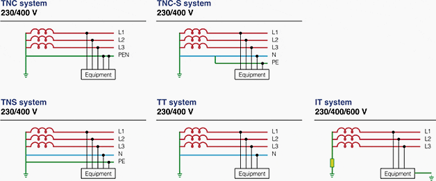
The more conventional earthing arrangements are:

  • TN-C where the earth and neutral are combined (PEN) and
  • TN-S where they are separated (5 wire) or
  • TN-C- S.

The latter is very common as it allows the single-phase loads to be supplied by phase and neutral with a completely separate earth system connecting together all the exposed conductive parts before connecting them to the PEN conductor via a main earthing terminal which is also connected to the neutral terminal.

Earthing concepts

Earthing concepts


For protective conductors of the same material as the phase conductor the cross-sectional area shall be the same size as the phase conductor up to 16 mm2. IMPORTANT: When the phase conductor is above 16 mm2 then the protective conductor may remain at 16 mm2 until the phase conductor is 35 mm2, after which the protective conductor should be half the size of the phase conductor.

For conductors which are not of the same material the cross-sectional area shall be adjusted in the ratios of the factor k from Table 43A in BS 7671. The k factor takes into account the resistivity, temperature coefficient and heat capacity of the conductor materials and of the initial and final temperatures.

Lastly there is the TT system which uses mother earth as part of the earth return.

The neutral and the earthed parts are only connected together via an electrode system back to the source earth (and neutral). To check that conventional systems are satisfactory, i.e. that the protection operates on the occurrence of an earth fault, it is necessary to calculate the earth fault loop impedance (Zs) and ensure that the fault current through it will cause the protection to operate.

Cant see this video? Click here to watch it on Youtube.

This is quite a tedious process, involving as it does the calculation of the impedances afforded not only by the earth return but also by:

  1. The phase conductor
  2. Supply transformer
  3. Supply network
  4. Any neutral impedance.

This information must be requested early. The Electricity Distributor should be able to give the fault level or the equivalent impedance of the supply network and the manufacturer can provide the appropriate impedances for the transformer.

However, time will be required to obtain the answers so enquiries should be made at the commencement of the project.

The substation will house the circuit breakers of fuses for the main cable connections to the sub-distribution boards and motor control centres. These protective devices must discriminate with those further down the line nearer the ultimate loads. A system study must therefore establish the correct ratings of the substation equipment to discriminate with the distribution network.

Earthing of equipment should be electrically complete and confirmed mechanically sound and tight.

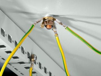
Earthing bolt on the switchboard roof

Earthing bolt on the switchboard roof


Earthing conductors (previously termed earth leads) must be checked for compliance with the IEE Regulations, i.e. they must not be aluminium and they must be not less than 25 mm2 for copper and 50 mm2 for steel, unless they are protected against corrosion. These conductors are for connection to the earth electrodes.

The protective conductors previously known as earth continuity conductors must also comply with BS 7671 (the IEE Regulations) and in general for phase conductors of less than 16 mm2; this means the protective conductors must be the same size as the phase conductors. When the phase conductor is above 16 mm2 then the protective conductor remains at 16 mm2 until the phase conductor is 35 mm2, after which the protective conductor should be half the cross-sectional area of the phase conductor.

Another important point to bring out is that the earthing conductor to the earth electrode must be clearly and permanently labelled ‘SAFETY ELECTRICAL CONNECTION – DO NOT REMOVE’ and this should be placed at the connection of conductor to the electrode.

Label: SAFETY ELECTRICAL CONNECTION – DO NOT REMOVE

Label: SAFETY ELECTRICAL CONNECTION – DO NOT REMOVE


Fuse ratings should also be checked in relation to other fuse ratings in the supply circuit or against the settings of protective relays to assure correct sequence of operation and discrimination. Circuit charts for distribution boards should be completed and designation labels fitted to ensure safe operation of switches and isolators.

All tests should be carried out as required in BS 7671, Part 7, and an Electrical Installation Certificate given by the contractor to the person ordering the work.

Many installations now incorporate rcds and fault current operated protective devices. These also must be tested using appropriate test equipment, full details of which can be found in BS 7671 or for more elaborate apparatus in BS 7430 and Guidance Notes which are published separately and amplify the requirements in the British Standard.

The nominal voltages at present are:

  • 230V + 10% and -6%
  • 400V + 10% and -6%

Reference: Handbook of electrical installation practice fourth edition – Eur Ing GEOFFREY STOKES


How to measure insulation resistance of a motor

$
0
0
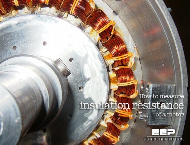
How to measure insulation resistance of a motor

How to measure insulation resistance of a motor (photo credit: elecls.cc.oita-u.ac.jp)

Winding insulation resistance

If the motor is not put into operation immediately upon arrival, it is important to protect it against external factors like moisture, high temperature and impurities in order to avoid damage to the insulation. Before the motor is put into operation after a long period of storage, you have to measure the winding insulation resistance.

If the motor is kept in a place with high humidity, a periodical inspection is necessary.

It is practically impossible to determine rules for the actual minimum insulation resistance value of a motor because resistance varies according to method of construction, condition of insulation material used, rated voltage, size and type. In fact, it takes many years of experience to determine whether a motor is ready for operation or not.

A general rule-of-thumb is 10 Megohm or more.

 Insulation resistance value Insulation level
 2 Megohm or less Bad
 2-5 Megohm Critical
 5-10 Megohm Abnormal
 10-50 Megohm Good
 50-100 Megohm Very good
 100 Megohm or more Excellent

The measurement of insulation resistance is carried out by means of a megohmmeter – high resistance range ohmmeter. This is how the test works: DC voltage of 500 or 1000 V is applied between the windings and the ground of the motor.

Ground insulation test of a motor

Ground insulation test of a motor


During the measurement and immediately afterwards, some of the terminals carry dangerous voltages and MUST NOT BE TOUCHED.

Now, three points are worth mentioning in this connection: Insulation resistance, Measurement and Checking.


1. Insulation resistance

  • The minimum insulation resistance of new, cleaned or repaired windings with respect to ground is 10 Megohm or more.
  • The minimum insulation resistance, R, is calculated by multiplying the rated voltage Un, with the constant factor 0.5 Megohm/kV.

    For example: If the rated voltage is 690 V = 0.69 kV, the minimum insulation resistance is: 0.69 kV x 0.5 Megohm/kV = 0.35 Megohm

2. Measurement

  • Minimum insulation resistance of the winding to ground is measured with 500 V DC. The winding temperature should be 25°C ± 15°C.
  • Maximum insulation resistance should be measured with 500 V DC with the windings at a operating temperature of 80 – 120°C depending on the motor type and efficiency.

3. Checking

  • If the insulation resistance of a new, cleaned or repaired motor that has been stored for some time is less then 10 Mohm, the reason might be that the windings are humid and need to be dried.
  • If the motor has been operating for a long period of time, the minimum insulation resistance may drop to a critical level. As long as the measured value does not fall below the calculated value of minimum insulation resistance, the motor can continue to run.

    However, if it drops below this limit, the motor has to be stopped immediately, in order to avoid that people get hurt due to the high leakage voltage.

Reference: Grudfos – Motor Book

Why is Continuous On-line Monitoring of Partial Discharge in the Switchgear Necessary?

$
0
0
Why is Continuous On-line Monitoring Partial Discharge in the Switchgear Necessary?

Why is Continuous On-line Monitoring Partial Discharge in the Switchgear Necessary? (on photo: 11kV voltage transfromer spout failure in progress – Located by Partial Discharge survey; by highvoltagesolution.com)

What’s the condition of your switchgear?

Not sure?

You know that periodical maintenance test like partial discharge test can still leave switchgear in virtually unknown condition. Insulation defects and deterioration may very well develop in service within maintenance cycle.

These defects are often not detectable with traditional off-line tests and yet, traditionally, on-line or off-line partial discharge tests have been performed on a periodic basis commonly twice a year.

Think this is often enough?

Advantages over periodic partial discharge (PD) testing

Continuous PD monitoring has the following advantages over periodic PD testing:

1. Periodic on-line PD test could miss significant PD activities since PD activities vary by time. On-line continuous monitoring eliminates the inherent flaw of interval-based testing.

2. Trending of PD activity is one of the most important parameters for predictive diagnostics. Periodic tests will not be able to provide sufficient information for diagnostics based on trending.

3. On-line monitoring provides more accurate information than off-line testing since off-line testing conditions can differ greatly from real operating conditions.

4. Continuous on-line monitoring effectively reduces labor costs. In addition, the PD data saved in the instrument can be accessed anytime, anywhere with modern communication means.

Partial discharge test performed on site

Partial discharge test performed on site (photo credit: epowerplus.com)

Degradation of Insulation in Switchgear

Electrical insulation is subjected to electrical and mechanical stress, elevated temperature and temperature variations, and environmental conditions especially for outdoor applications.

In addition to normal operating conditions, there are a host of other factors that may trigger accelerated aging or deterioration of insulation.

Switching and lightning surges can start ionization in an already stressed area. Mechanical strikes during breaker operation can cause micro cracks and voids. Excessive moisture or chemical contamination of the surface can cause tracking.

PD Between Bus and Cubicle Wall

PD Between Bus and Cubicle Wall


Any defects in design and manufacturing are also worth mentioning. Both normal and accelerated aging of insulation produce the same phenomenon in common – Partial Discharge (PD).

Partial discharge (PD) is a localized electrical discharge that does not completely bridge the electrodes. PD is a leading indicator of an insulation problem. Quickly accelerating PD activity can result in a complete insulation failure.

Partial discharge mechanism

PD mechanism can be different depending on how and where the sparking occurs:

  1. Voids and cavities are filled with air in poorly cast current transformers, voltage transformers and epoxy spacers. Since air has lower permittivity than insulation material, an enhanced electric field forces the voids to flashover, causing PD. Energy dissipated during repetitive PD will carbonize and weaken the insulation.
  2. Contaminants or moisture on the insulation induce the electrical tracking or surface PD. Continuous tracking will grow into a complete surface flashover.
  3. Corona discharge from sharp edge of a HV conductor is another type of PD. It produces ozone that aggressively attacks insulation and also facilitates flashover during periods of overvoltage.


Reference:  Predictive Diagnostics for Switchgear – EATON

Testing of Power Transformer – Measurement of Zero-Sequence Impedance

$
0
0
Testing of Power Transformer - Measurement of Zero-Sequence Impedance

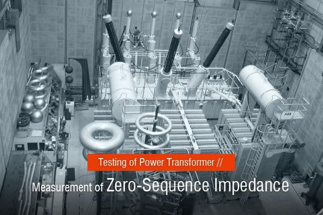
Testing of Power Transformer – Measurement of Zero-Sequence Impedance (on photo: preparing the 400 kV transformer for the test field inside the ABB’s factory)

Earth-fault protection

Purpose of the measurement

The zero-sequence impedance is usually measured for all star-connected windings of the transformer. The measurement is carried out by supplying a current of rated frequency between the parallell connected phase terminals and the neutral terminal.

The zero-sequence impedance per phase is three times the impedance measured in this way.

The zero-sequence is needed for earth-fault protection and earth-fault current calculations.

Measuring circuit and performance of measurement

Circuit for zero-sequence impedance measurement in shown below, where:

  • G1 = supply generator
  • T1 = transformer to be tested
  • T2 = voltage transformer
  • T3 = current transformer
  • P2 = voltmeter
  • P3 = ammeter
  • I = test current
Figure 1 - Circuit for zero-sequence impedance measurement

Figure 1 – Circuit for zero-sequence impedance measurement


The zero-sequence impedance is dependent on the current flowing through the winding. Usually the value corresponding to rated current IN is stated. This implies that the measurement is carried out with a test current of 3 x IN.

However, this is not always possible in practice since the current must be limited to avoid excessive temperature of metallic constructional parts.

The zero-sequence impedance is measured as function of test current, and when necessary the final result is obtained by extrapolation.

Test Result

The zero-sequence impedance is usually given as a percentage of the rated phase impedance.

When the transformer has a three-limb core and no delta-connecter windings, the zero-sequence impedance is about 30…60 %. When the transformer has a delta-connected winding, the zero-sequence impedance is 0.8…1.0 times the corresponding short-circuit impedance.

In the test report the zero-sequence impedance values at the principal and extreme tappings are stated.

Reference: Testing power transformers – ABB

Transformer Routine Test – Partial Discharge Measurement

$
0
0
Transformer Routine Test - Partial Discharge Measurement

Transformer Routine Test – Partial Discharge Measurement (on photo: OSB Power Transformers Test Laboratory by BEST Transformers)

Transformer insulation structure

This routine test aims to measure the partial discharges which may occur in the transformer insulation structure during test.

Partial-discharges are electrical arks which form the surges between electrodes of any area of the insulating media of a transformer between the conductors. These discharges may occur in air bubbles left in the insulating media, gaps in the solid materials or at the surfaces of two different insulators.

Although these discharges have small (weak) energy, the thermal energies due to these discharges can cause aging, deformation and tear of the insulating material.

The following conditions can be determined during partial-discharge measurement:

  1. To determine whether a partial-discharge above a certain value has occurred in the transformer at a pre-defined voltage.
  2. To define the voltage values where the partial-discharge starts by increasing the applied voltage (partial-discharge start voltage) and the value where the partial-discharge ceases by decreasing the applied voltage (partial-discharge cease voltage).
  3. To define the partial-discharge strength at a pre-defined voltage.

How Partial-Discharge occurs and measured magnitudes?

The structure where a partial-discharge occurred in an insulating media is shown in the simplified Figure 1. As seen on the simpliified diagram, the impulses forming on the discharge point cause a ΔU voltage drop at the transformer line terminals. This forms a measurable “q” load at the measuring impedance.

This load is called apparent load and given in pC (Pico-Coulomb) units.

During measurements: ΔU voltage drop, average value of apparent partial-discharge current, partial- discharge power, impulse count within a time unit, partial-discharge start and cease voltages can also be determined.

a) simple schematics of an insulator with gas gap b) equivalent circuit

Figure 1 – a) simple schematics of an insulator with gas gap b) equivalent circuit

Measuring circuit and application

Partial-discharge measurement structure of a transformer and related circuit in accordance with IEC 60270 is explained below.

Partial discharge measuring connection circuit

Figure 2 – Partial discharge measuring connection circuit


Where:

1. Supply generator
2. Supply transformer
3. Test transformer
4. Voltage transformer and measuring circuit
5. Filter
6. Measuring impedance
7. Selective switch
8. Measuring instrument and ossiloscope
qo - calibration generator

The measurement circuit in Figure 2 is formed according to Bushing-tap method stated in standards.

Before starting to measure, complete measurement circuit should be calibrated.

For this, a calibrator (Calibration generator) is necessary. The calibrator produces a q0 load with a predefined value. Calibrator is connected to the test material in parallel. The q0 load produced in the calibrator is read at the measuring instrument. These steps are repeated at all terminals of the transformer to be measured at no-voltage.

K = q0 / q0m

Where:

K – correction factor
q0 – load at the calibrator
q0m – load read at the measuring instrument


Application of the test

After the calibration operations are completed, the calibration generator is taken away from the measuring circuit. When the power system is connected (supply generator switch is closed), the voltage level will be too low (remenance level).

This value which is considered as the base noise (interference) level of the measuring system should be less than half of the guaranteed partial- discharge level.

Voltage level

The voltage is substantially increased up to the level stated by the specifications and in the meantime the partial-discharge values at the predefined voltage levels are measured at each measuring terminal and recorded. The voltage application period, level and measuring intervals are given in the induced voltage test section.

After the transformer is energised for measuring operations, the partial-discharge value read at the measuring instrument is multiplied with the predefined K correction factor, and real apparent partial-discharge value for each terminal is found.

q = K · qm

Where:

  • qm – load read at the measuring instrument m
  • K – correction factor
  • q – Real apparent load

Evaluation

The test is considered to be succesful if the partial-discharge value measured at the transformer’s measuring terminals is lower than predefined values or values stated in the standards and no increasing tendency is observed during test.

In addition to the measured partial-discharge level, the below conditions should also be considered in transformers:

  • Partial-discharge start and cease voltages are above the operating voltage.
  • Depending on the test period, partial-discharge level stays approximately stable.
  • Increasing the test voltage causes almost no partial-discharge level change.

Reference: Transformer Tests – BEST Transformers

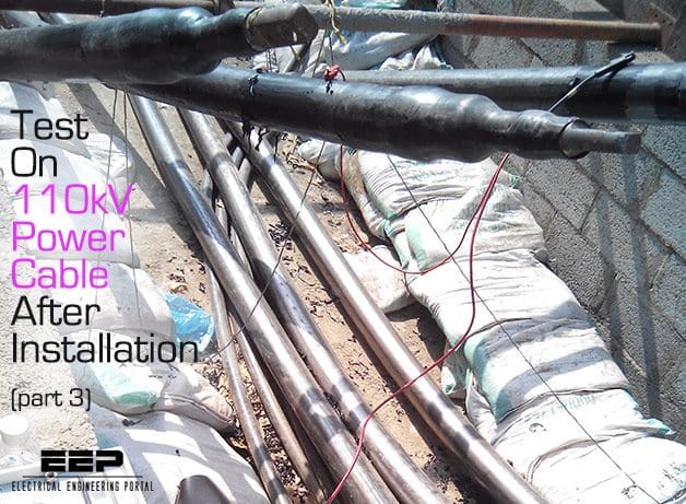
Test On 110kV Power Cable After Installation (1)

$
0
0
Test On 110kV Power Cable After Installation (1)

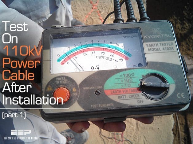
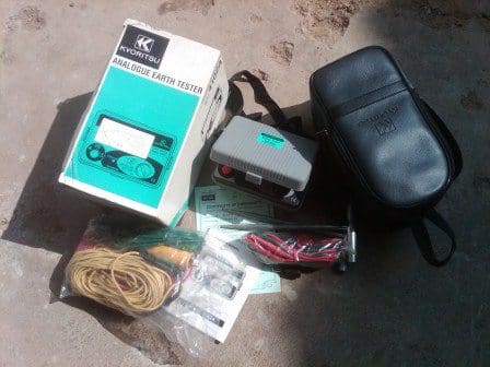
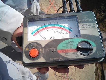
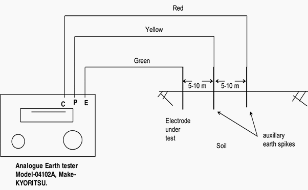
Test On 110kV Power Cable After Installation – Part 1 (on photo: Kyoritsu 4102A digital earth resistance tester)

General description of site test procedure

Site test procedure covers all necessary electrical testing for the 110 kV cable and accessories to be carried out during and after installation of the cable system.

This procedure is in line with the requirements of the contract suitable for 110 kV, XLPE cables and accessories and the tests are in accordance with TCSP-104.08, IEC 229, IEC 540 and IEC 840.

110 kV, 115 kV and 132 kV XLPE Cables

(Standard Reference is IEC 60840 and relevant SEC Transmission Specifications 11-TMSS-02, Rev. 0 and TCS-P-104.02, TCS-P-104.03, TCS-P-104.06 and TCS-P-104.08)

1. Mechanical Check and visual Inspection

ITEMDescriptionRemark
1Inspection for physical damage or defects
2Check tightness of all bolted connections (torque wrench method)
3Check for proper cable bolted connections
4Check cable bends to ensure that bending radius is equal to or greater than the minimum bending radius specified
5Check for proper cable support, clamping, trays arrangements
6Link box tightness check
7Verify that shields are terminated as specified (through link box or directly grounded)
8Verify the exact route length as per approved drawings from terminations to terminations
9Check that all grounding points are securely connected to ground grid as specified
10Check that phases are identified and color coded
11Single core cable connected between power transformer and switchgear shall be single point earthed as switchgear side and at floating side SVL (sheath voltage limiter) should be installed
12Check single point or both ends, via voltage limiter as per approved design
13Inspection of label inside link boxes and water proofing
14Check cable entry path trench as ducts are properly sealed
15Check irregularities of outer jacket formed by non-uniform shield wire distribution
16Check/inspect the transposition of cable phases
17Check the cable outer jacket for any physical damage during and after installation
18Check for the cross connection of cable metallic sheath in cross bonding system
19Check the rubber seal in cable clamps to avoid any damage to cable outer jacket
20Check the insulating shrouds are installed at the base of the cable terminations
21For accessories (sealing terminations, instrument panels and link boxes) check the following:
a. Name plates installed and data is correct
b. Danger signs
c. Bolt tightness check and paint work conditions

2. Electrical Test

(Standards Reference is IEC 60840, and relevant SEC Transmission specifications 11-TMSS-02, TCS-P-104.08).

ITEMDescriptionRemark
1Check Phasing for Conductor and sheath bonding
2Sheath DC high voltage test (10 kV DC for 1 min.) and 5 kV DC insulation test before and after high voltage/24 hour soaking test
3Conductor resistance, capacitance and inductance measurement test
4Conductor insulation resistance test
5Cross-bonding verification testThe sheath current should be <3% the current due to induction neighboring circuits should be considered and limit should be 3%+current due to external circuits
6Zero and positive sequence impedance measurement
7SVL (Sheath/Surge voltage Limiter) test by 2.5 kV DC insulation tester
8Measure the ground resistance at all link box positions as per SEC standards TES-P-104.08)
9Contact resistance test on link boxes (less than 20 μΩ)
10Metallic sheath continuity test
11Cable profile test- during jointing
12In case of Double Circuit (110 kV and above), check the separate grounding pit
13AC High voltage test for all new cables, but if old portion are involved then soaking for 24 hours at rated voltage
1. Phase indication test

After complete installation, the cables are to be identified with respect to their phases and are to be reconfirmed whether they are correctly marked or not.

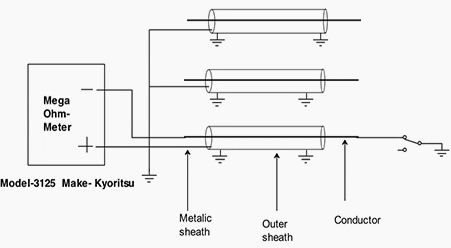
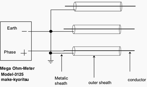
Phase Identification Test diagram

Phase Identification Test diagram

Equipment / Instruments Used

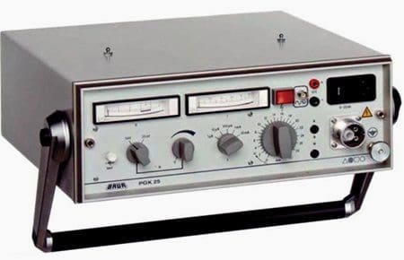
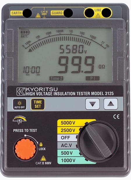
Battery operated KYORITSU, High Voltage Insulation Resistance Tester, and MODEL-3125

Kyoritsu 4105A - Digital Earth resistance tester

Kyoritsu 4105A – Digital Earth resistance tester


Instructions

  1. The screens of all cables at one end are to be shorted and grounded.
  2. The conductor of the cable under test is to be connected to the negative pole of the meter.
  3. The positive pole of the meter is to be grounded.
  4. Through a switch ground the other end of this conductor of the cable under test and measure the resistance.
  5. If the resistance becomes zero, the phase identification is ok and checks whether the correct color coding is applied or not.
  6. To cross check, open the switch, the meter shall read high resistance (Tending to infinity).
  7. Similarly repeat the test for other phases and verify the correctness of color coding.

2. DC Conductor Resistance Measurement

The DC resistance of conductors of the cables, to be measured at ambient temperature before conducting any other test, and the values are to be computed for 20ºC.

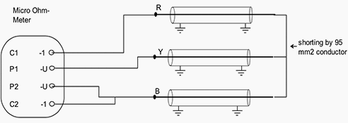
Schematic layout for measurement of DC resistance for long cable

Schematic layout for measurement of DC resistance for long cable

Reference

  • IEC 60228 – Conductors of insulated cables

Equipment / Instruments used

  1. Any wheatson bridge, micro Ohm-Meter.
  2. Any industrial type thermometer to measure the ambient temperature.

Instructions

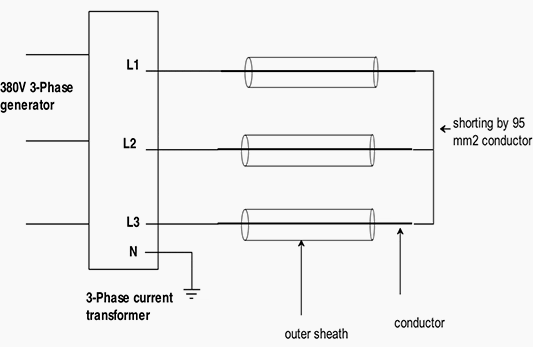
  1. The conductors are short circuited at the far end by minimum 95 mm2 cable.
  2. The other ends of the cable are connected to the bridge according to equipment instructions.
  3. Note down the measured value.
  4. The resistance of conductor at 20ºC/km is obtained by substituting the measured value in the formula.
Formula for Temperature Correction:

For Copper R20 = R/L (1 + 0.00393*(T-20)) Ω/KM

Where,

  • R20 – Conductor resistance at 20ºC *(ohm/km
  • R – Measured resistance of one phase (ohm)
  • L – Exact length (km)
  • 0.00393 – Temperature coefficient at 20ºC for copper (K)
  • T – Temperature of conductor when measured in ºC


3. Capacitance Test

The capacitance shall be measured between conductor and metallic screen. According to IEC, the measured value shall not sxceed the normal value specified by the manufacturer by more than 8%.

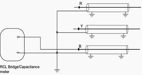
Schematic layout for capacitance measurement

Schematic layout for capacitance measurement

Reference

  • IEC 60840 – Applies to cable voltage ratings between 30 kV and 150 kV. It includes a regular type test sequence for cables and a separate sequence for the cable accessories.

Equipment / Instruments used

Any RLC bridge capable of measuring capacitance up to 0.01 micro-farad (μF)

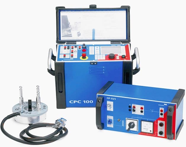
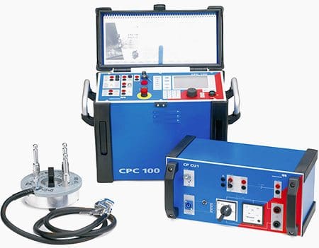
Omicron - for zero positive sequence test and capacitance measurements

Omicron – for zero positive sequence test and capacitance measurements


Instructions

  • Connections are made as per below schematic.
  • Connect the instrument cable between conductors and metallic screen and take the measurements.
  • The capacitance is measured between each individual conductor and sheath. A capacitance bridge is used for this measurement.
  • The value obtained can be converted to μF/km
Formula for Capacitance:

C = Cm/L (μF/km)

Where:

  • C – Capacitance in μF/k
  • Cm – Measured Capacitance in μF
  • L – Length of Cable in km.

To be continued soon…

Test On 110kV Power Cable After Installation (2)

$
0
0
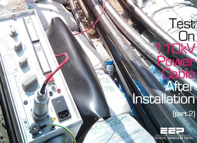
Test On 110kV Power Cable After Installation (Part 2)

Test On 110kV Power Cable After Installation (Part 2)

General description of site test procedure

In previous part of this technical article first three procedures were explained. Now the rest will be explained in details:

  1. Phase indication test (previous part)
  2. DC conductor resistance measurement (previous part)
  3. Capacitance test (previous part)
  4. DC Sheath test on outher sheath
  5. Insulation resistance measurement
  6. Cross bonding check
  7. Zero sequence and positive sequence impedance test (next part)
  8. Earth resistance measurement at link boxes (next part)
  9. Link box contact resistance measurement (next part)

4. DC sheath test on outher sheath

The test is applied when the cable sheath can be isolated from the earth to permit a voltage to be applied to the over-sheath to check the integrity of the covering.

This testing is generally applied at certain stages of cable system installation at specified parameter as follows:

  1. When the cable is still on reel. The applied test voltage is 10 kV for 10 seconds, if a proper test lead is provided.
  2. Once the cable are laid, dressed and tied together in trefoil configuration a test voltage of 10 kV for 30 seconds is applied.
  3. Following backfilling sand beddind-2, a test voltage of 10 kV is applied for 1 minute on each cable. This is a formal testing with test records and signed by representatives of the responsible parties as witnesses.
  4. Following completion of jointing activities between two cable sections in a joint bay and after backfilling of the joint bay, the jointed cable sections are then tested by applying 10 kV for 30 seconds.
  5. Following the completion of cable system installation and prior to acceptance testing, as a pre-check testing a test voltage of 10 kV is applied for 1 minute.
Note – All above mentioned testing will be conducted in presence of project consultant.

References

  • IEC 60840 - Power cables with extruded insulation and their accessories for rated voltages above 30 kV
  • IEC 60229 - Electric cables // Tests on extruded oversheaths with a special protective function
  • TES-P-104.08 – Bonding and grounding of insulated metallic sheath of power cable system

Equipment / Instruments used

The DC HV 25kV Tester, Model No. PGK 25 manufactured by BAUR Germany. The test is applied only to cables covered with conductive layer over outer sheath. (Read more about Hipo Testing)

DC Hipo Tester, BAUR PGK 25

DC Hipo Tester, BAUR PGK 25

Instructions

  1. The covering under sheath is exposed about 2 cm length at one end of the cable so that the negative polarity shall be applied to it.
  2. The conductive layer on outer sheath shall be removed about 20 cm wide at a distance of 30 cm from both ends of the cable.
  3. The positive terminal of the DC source is connected to a copper band wound on the conductive layer of the sheath at one end of the cable (60 cm away from the end).
  4. The 25 kV tester can be operated by choice either from the power supply source of 220/110 v- 50/60 Hz supply or can be charging its in-built battery set-up.
  5. Switch on the timer in clockwise direction, a lamp indicator will be indicated ‘ON’ position to a desired test period.
  6. Select the voltage selector switch to 5 kV or 25 kV.
  7. Select the range of current measurement to position corresponding to the current value intended for charging the test cable.
  8. Slowly rotate the voltage selector to the desired voltage value on the scale (1 kV per second in intervals). Watch carefully the voltmeter while charging. If required re-adjust voltage selector before the desire test voltage is reached.
  9. Set range switch for current measurement to the desire range after charging has been completed.
  10. After the time has elapsed the high voltage bring down to zero, switch off the timer and discharge the cable through ground wire.
DC Sheath Test diagram

DC Sheath Test diagram

Requirements

The cable is considered to have passed if it withstands the required voltage (10 kV) during the test for 1 minute without break down. During the test, the leakage current shall be recorded. During the testing, safety regulations on electric hazards should be strictly observed. The measurements / reading are recorded in the available format in company.

Go back to Index ↑


5. Insulation resistance measurement

The insulation resistance shall be measured between conductor and metallic screen according to IEC 60840.


References

  • IEC 60229 - Electric cables – Tests on extruded oversheaths with a special protective function
  • TES-P-104.08 - Bonding and grounding of insulated metallic sheath of power cable system

Equipment / instruments used

Battery operated -KYORITSU High Voltage Insulation Resistance Tester, and MODEL-3125.

KYORITSU High Voltage Insulation Resistance Tester

KYORITSU High Voltage Insulation Resistance Tester

Instructions

  1. Cable should be free from all system connections
  2. Connect the cables between conductor and metal sheath.
  3. Measure the resistance at the required voltage and charging time (1 minute).
Insulation resistance test diagram

Insulation resistance test diagram

The insulation resistance (Ri) measured between each individual conductor and metal sheath. The insulation resistance per kilometer is calculated from:

Rl = Ri x L (GΩ Km)

Where:

Rl – Insulation resistance in GΩ Km.
Ri – Measured insulation resistance in GΩ.
L – cable length in Km.

Go back to Index ↑


6. Cross bonding check

With the cross bonding checks, the right connection of the cables can be checked and when correctly bonded, no current may flow in the metal sheath of the cable in case of an ideal situation.

Ideal case is only the case when all cable sections have the same length and the spacing between the cables is constant along the cable route. But in practice, some induction current will always flow as the configuration of the cable system is never ideal.

The actual site requirements and situation dictate what the actual cable section lengths that may differ from section to section.


Equipment / Instruments used

  • 380 V Generator
  • 3-Phase Current Transformer
  • Clamp Meter

Instructions

  1. Screen is to be grounded at both ends.
  2. The conductors are short circuited at the far end firmly by minimum 95 mm2 cable.
  3. The conductors under test are connected as shown in figure below.
  4. Increase the current gradually insteps by balancing the phases individually to desired value.
  5. Note down the current induced in all the link boxes.
  6. Reduce the current gradually and switch off the breaker.
Cross bonding check diagram

Cross bonding check diagram


Go back to Index ↑

Will be continued soon…

Test On 110kV Power Cable After Installation (3)

$
0
0
Test On 110kV Power Cable After Installation (Part 3)

Test On 110kV Power Cable After Installation (Part 3)

General description of site test procedure

In previous two parts of this technical article first six procedures were explained. Now the last three (7, 8 and 9) will be explained in details:

  1. Phase indication test (part 1)
  2. DC conductor resistance measurement (part 1)
  3. Capacitance test (par 1)
  4. DC Sheath test on outher sheath (part 2)
  5. Insulation resistance measurement (part 2)
  6. Cross bonding check (part 2)
  7. Zero sequence and positive sequence impedance test
  8. Earth resistance measurement at link boxes
  9. Link box contact resistance measurement

7. Zero sequence and positive sequence impedance test

Positive sequence impedance are calculated assuming that there are no metallic elements that are placed within an influential distances of cable (Railway lines, pipe lines or buried equipment’s etc.).

The presence of other metals or metallic objects influences the sequence impedance. Because of influence of other unknown factors, it is recommended that the impedance should be measured in the field after the circuits are installed. Positive and negative sequence impedance for cables is same value, because the impedance of these in uncharged if a symmetrical voltage system with reverse sequence is applied to them.

Zero sequence impedance of the cable is not a fixed parameter and depends on the kind of transmission and electrical conductivity of the soil (environment). Measurements on installed cables have to be carried out, in order to obtain the exact value.

Usually the zero sequence impedance can be assumed as 3 times the positive sequence impedance value as a practice for initial approximation.

The three currents of zero sequence system, equal in magnitude and direction, are opposed by an impedance that is determined by the loops formed by the three cable cores and returned by the metallic sheaths and earth in parallel. The effective AC resistance of the zero sequence system includes both the effective resistance of the line conductor as well as that of earth return.

The zero sequence impedance can be determined by measurement or calculation when the three phase of the system are connected in parallel and single phase AC current is applied to them.


Instruments / Equipment used

  • 3-phase variable transformer (up to 100 Amps supply capacity).
  • Impedance measurement equipment – Digital.
CP-CU1 Omicron for Zero positive sequence test and capacitance measurements

CP-CU1 Omicron for Zero positive sequence test and capacitance measurements

Instructions

Measurement of positive/negative sequence impedance:

  1. The measurement is done between two phases of the circuit once the complete circuit is installed, cable may be transposed and cross bonded between the terminations. There should be electric accessibility to the cable cores at terminations.
  2. The connections should be made as per Figure 1A.
  3. Turn up the power with the variable transformer until 25 Amps of current starts flowing. Switch the impedance measurement equipment and record the voltage, current and angle (power factor).
  4. Switch off after the measurement and turn the variable transformer down.
  5. The measurement is to be repeated three times: between R & Y, between R & B and between Y & B phases.

Measurement of zero sequence impedance

  1. The measurement is done by connecting the three phases of circuit connected in parallel and a single phase AC voltage is applied to them.
  2. The connections should be made as per Figure 1B.
  3. Turn up the power with the variable transformer until 25 Amps of current starts flowing. Switch the impedance measurement equipment and record the voltage, current and angle (power factor).
  4. Switch off after the measurement and turn the variable transformer down.
  5. Repeat for each phase.
Precautions: safety precautions should be taken prior to switching by putting up warning tapes and stationing personnel at critical point to ensure that no one is within reach of system parts where high current are applied.

Schematic diagrams

Schematic layout for measurement of Positive/Negative Sequence Impedance

Figure 1A – Schematic layout for measurement of Positive/Negative Sequence Impedance


Schematic layout for measurement of Zero Sequence Impedance

Figure 1B – Schematic layout for measurement of Zero Sequence Impedance


Go back to Index ↑


8. Earth resistance measurement at link boxes

The measurement of earth resistance is mainly intended for the purpose of grounding the links of bonding system of high voltage cable screen.


Equipment / Instruments used

Analogue Earth tester Model-04102A, Make-KYORITSU.

Analogue Earth tester Model-04102A, Make-KYORITSU

Analogue Earth tester Model-04102A, Make-KYORITSU

Instructions

  1. Check the battery voltage, set the range switch to battery check position and press test button and make sure the indicator is at right of BATT GOOD position.
  2. The connections as per the figure bellow.
  3. Check the earth voltage by setting switch to earth voltage position, make sure the voltage is 10V or less. If the earth voltage is higher, the result may be with excessive high errors.
  4. Measure the earth resistance by setting the switch to resistance range position and press test button.
  5. The earth resistance must not exceed 5Ω for outside substation and 3Ω for inside substation.

Schematic diagram

Earth resistance measurement at link boxes

Earth resistance measurement at link boxes

9. Link box contact resistance measurement

This test is basically carried out after installation of link boxes and connecting leads.


Equipment / Instruments used

  • Megger DLRO-200 for contact resistance and DC resistance measurements
Megger DLRO-200 for contact resistance and dc resistance measurements

Megger DLRO-200 for contact resistance and dc resistance measurements

Instructions

  1. All the bolts are to be tightened firmly
  2. Connect the micro-ohmmeter with the link box as shown in figure below.
  3. The micro-ohmmeter shall be applied between earth copper bar and each disconnect able copper bars.
  4. Test shall be repeated for individual connections.
  5. The values should bein micro-ohm range.

Schematic layout

Link box contact resistance schemetic layout

Link box contact resistance schemetic layout


Go back to Index ↑


Inspection, Test and Measurement Procedures for LV and MV (up to 36kV) Switchgears

$
0
0
Inspection, Test and Measurement Procedures for LV and MV (up to 36kV) Switchgears (on photo" Eaton Cutler Hammer Magnum DS Switchgear Inspection, and Transformer Testing)

Inspection, Test and Measurement Procedures for LV and MV (up to 36kV) Switchgears (on photo” Eaton Cutler Hammer Magnum DS Switchgear Inspection, and Transformer Testing)

Importance of checks and maintenance

Installed in clean, well ventilated or air-conditioned locations, switchgear will require little routine maintenance.

Major inspection should be scheduled for power plant shutdowns and concentrate for low voltage switchboards on identifying contact wear, correct operation of interlocks, correct overload settings and fuse sizes, signs of overheating, and undue dirt or corrosion. For MV switchgear similar considerations apply although more extensive checks on protective devices, circuit breaker oil, vacuum bottle contact distances are required as specified by the Manufacturer.

Exceptions to the above rule are devices which operate frequently, where inspection/overhaul may need to be based on the number of operations. Also, MV isolating devices which have cleared a short circuit will require confirmation that the insulating medium and the circuit contacts are fit for continued service.

Gas Insulated Switchgear (GIS) shall be maintained in accordance with the manufacturer’s recommendations. Where extensive (intrusive) maintenance is required, the Manufacturer should be involved in the activity.

For older switchgear, a condition assessment should be performed to establish that the equipment remains in a suitable condition for further service.

Partial discharge testing and infrared scanning can be used to obtain data on the performance of the insulation system and the integrity of the switchgear busbars and cable terminations. The frequency of such tests will depend on the duty, age and condition of the switchgear.

Infrared partial discharge testing

Infrared partial discharge testing (photo credit: reliabilityweb.com)


NOTE //

The effectiveness of infra-red scanning depends on the ability to access the current-carrying components under loaded condition. Scanning through metallic enclosures has generally proved ineffective. Removal of enclosures of live equipment may not be possible without compromising electrical safety.


LV switchgear

TypeDescriptionIntervalExtent
1. INSPECTIONGeneral external condition.1 yAll
Motor starters and outgoing feeders, internal.
Incomers, internal.
4 y
Busbar compartments (1).8 y
Metering:
- Correctness main voltmeters.
- Correctness main ammeters.
4y
General internal condition of outdoor equipment (5).2 y
2. TEST AND
MEASUREMENT (3)
Incoming feeders, bus section, switches:
- Operating mechanism.
- Interlocks.
- Control equipment.
- Electrical protection/tripping (2).
4 yAll
Busbar systems:
- Torque bolts (1).
- Insulation resistance.
- Continuity (ductor).
8 y
Motor feeders:
- Draw-out system/interlocks.
- Cable connection tightness.
4 y
Thermal and earth fault protection.4 y10%
Certified Ex ‘e’ thermal protection (4).3 yAll
Restart system.4 y10%
Insulation resistance of motor + cable.4 yselected
Plain feeders:
- Draw-out system/interlocks.
- Cable connection tightness.
4 yAll
Protection/tripping. (2)4 y10%
R.C.D. for fixed load (e.g. trace heating).4 yAll

NOTES:

  1. Access to modern, high integrity, insulated/segregated busbar systems may be difficult. In this case other test and measurements as indicated should give sufficient information on the actual condition.
  2. CT connected protection relays should be tested by means of secondary injection.
  3. Testing of change-over systems of emergency switchboards should coincide with the testing of the emergency generator/system.
  4. Type of protection ‘e’. Motor protection devices are selected so that the tripping time from hot when the locked rotor current of the motor is carried, is carried with the motor in the stalled condition, is less than the time tE on the motor nameplate.
  5. Internal inspection should be limited to contactor/control equipment installed out of doors in boxes, e.g. MOV control panels.

MV switchgear (up to 36 kV)

TypeDescriptionIntervalExtent
1. INSPECTIONGeneral external condition.1 yAll
Cable boxes internal.
Circuit breakers internal.
Fused contactors internal.
4 y
Busbar compartments (1) internal.8 y
Metering:
- Correctness of main voltmeters.
- Correctness of main ammeters.
- Correctness of other measuring  systems.
4 yAll
2. TEST AND
MEASUREMENT (3)
Circuit breakers in/outgoing and fused
contactors (3):
- Operating mechanism.
- Draw-out system/interlocks.
- Control equipment.
- Insulation resistance
4 yAll
Dielectric strength across open  contacts.8 y
Ductor test across closed contacts.
Electrical protection/tripping (2).
4 y
Certified Ex’e’ thermal protection (4).3 y
Contact distance.4 yVacuum, SF6
Dielectric test oil.4 yOil-immersed
Insulation resistance of cable (incl.  motor if applicable).4 y All
Restart system.4 y Motors
Busbar systems:
- Torque bolts (1).
- Insulation resistance.
- Dielectric strength.
- Continuity (ductor).
 8 yAll
Correctness of kW, kVAr, max.
demand of measuring systems (5).
 4 y
3. RESTORATIONGreasing of operating mechanisms. 4 yAll
Oil filtering/replacement.
Component replacement.
As necessary

NOTES:

  1. Access to modern, high integrity, insulated/segregated busbar systems may be difficult. In this case other test and measurements as indicated should give sufficient information on the actual condition.
  2. CT connected protection relays should be tested by means of secondary injection.
  3. After operation of the circuit breaker/contactor following a short circuit, the proper operation of switching device and its protection shall be tested.
  4. Type of protection ‘e’.
    Motor protection devices are selected so that the tripping time from hot when carrying the locked rotor current of the motor is carried, with the motor in the stalled condition, is less than the stated time tE on the motor nameplate.
  5. Where used for tariff purposes.

Reference: Field commissioning and maintenance of electrical installations and equipment // DEP 63.10.08.11-Gen.

Basic Transformer Routine Test – Measurement of Winding Resistances

$
0
0
Measurement of the transformer winding resistances

Measurement of the transformer winding resistances (photo credit: colvininfrared.com)

Purpose of the measurement

The resistance between all pairs of phase terminals of each transformer winding are measured using direct current. Furthermore the corresponding winding temperature is measured.

The measured resistances are needed in connection with the load loss measurement when the load losses are corrected to correspond to the reference temperature. The resistance measurement will also show whether the winding joints are in order and the windings correctly connected.


Apparatus and basic measuring circuit

The measurement is performed by TETTEX 2285 transformer test system.

Tettex 3 Channel Winding Resistance Meter

Tettex 3 Channel Winding Resistance Meter


This device is an automatic winding analyzer, optimized for three phase power and distribution transformer measurements.

Circuit for resistance measurement

Figure 1 – Circuit for resistance measurement

Where:

  • T1 - transformer under test,
  • A – Ammeter,
  • U – Voltmeter
  • B – DC supply,
  • Th - Thermometer

The principle of the measurement is as follows:

The voltage drop Udc caused by the direct current Idc an by the resistance RAB, RAC and RBC is measured.The resistances are then calculated from Udc and Idc using correction for the error caused by the internal resistance of the voltage measuring equipment.

The temperature is measured from oil filled thermometer pockets situated in the transformer cover by means of an electronic thermometer connected to the computer.


Test report

The resistance values and the average temperature are calculated. In the report the terminals, between which the resistances are measured, the connection, the tapping position and the average temperature of the windings during the measurement are stated.

Reference: Testing of power transformers – ABB

Do Not Energize Oil-Filled Transformer Without Performing These 15 Tests and Checks!

$
0
0
Do Not Energize Oil-Filled Transformer Without Performing These 15 Tests and Checks!

Do Not Energize Oil-Filled Transformer Without Performing These 15 Tests and Checks! (on photo 3-core type oil-immersed rectifier transformer 380kV; via electric-power-transformers.com)

Obligatory Checklist

The following tests and checks should be performed at a minimum to ensure that the transformer is ready to be energized. Do not energize the transformer without performing these tests and checks.

If any of below explained tests fail and transformer is energized anyway, it may lead to the serious hazard, and that’s not good ;) That’s not what we want.

Let’s see these 15 tests…


1. Insulating Fluid Test

Draw a fluid sample and test its dielectric strength. Dielectric strength of new fluid should be 26 kv or greater.

How well insulating oil can withstand an electrical load

The breakdown voltage indicates how well insulating oil can withstand an electrical load and is therefore decisive for the operational efficiency of a transformer. The breakdown voltage is measured according to VDE 0370 part 5 (IEC 60156); photo credit: SIEMENS

2. Pressure Test

Check the transformer tank for leaks by pressurizing the tank with dry air or dry nitrogen through the pressure test fitting to a pressure of 3 to 4 PSIG. let the tank stand under pressure for one to two hours, then examine the tank and fittings for leaks. leaks above the fluid level can be detected by applying soap solution to all welds, joints, pipe fittings, and cable connections.

Upon completion of this test, reduce the internal pressure to 1 or 2 PSIG.

Repairing transformer oil-tank for leakage

Repairing transformer oil-tank for leakage (photo credit: khia.belzona.com)

3. Insulation Megger Test

Perform a 1000-volt Megger test and a power factor test to ensure that none of the windings is grounded. See the complete procedure here.

Regular insulation testing is one of the most cost effective methods of identifying aging  of transformer

Regular insulation testing is one of the most cost effective methods of identifying aging of transformer

4. Ratio Test

Perform a ratio test at each tap position to ensure that transformer coil ratios and tap changer connections are correct. Read the complete procedure of transformer turns ratio test step by step.


5. Continuity Test and Resistance Test

Perform a continuity check on each winding. Measure the winding resistance of each winding and compare results to factory test values.

An increase of more than 10% could indicate a loose internal connection.

6. Line Connections

In preparation for making line connections, check to make sure that all mating connector surfaces are clean and smooth. Connections must be tightened appropriately to prevent overheating and possible subsequent failure of the connection.

Connections to should be made with care to avoid placing undue stress on the bushings.

Oil-filled transformer bushings

Oil-filled transformer bushings (photo credit: khia.belzona.com)

7. Tap Changer Setting

Check the tap changer setting to ensure it is set to the proper position for the required voltage. See an example of transformer tap-changer correct adjustment.

On-Line Oil Filtration for Load Tap Changer Compartment

On-Line Oil Filtration for Load Tap Changer Compartment (photo credit: velcon.com)

8. Delta/Wye and Series/Multiple Switch Settings

Check delta/wye and series/multiple switch settings to make sure they are set correctly.

If these connections are made using an internal terminal board, check to ensure that these connections are made properly according to the chart on the transformer nameplate.

GE distribution transformer nameplate

GE distribution transformer nameplate (photo credit: tucsontransformer.com)

9. Grounding

Check to ensure that the transformer tank is permanently and effectively grounded. The transformer tank ground pad is located near the bottom of the tank.


10. Wiring

Check wiring of control and alarm circuits (if provided) to make sure there are no loose connections and no damage to insulation.

Oil-filled transformer terminal box

Oil-filled transformer terminal box

11. Fluid level

Liquid Level Gauge

Figure 1 – Liquid Level Gauge


Check to make sure the fluid level as indicated by the fluid level gauge is as follows:

The fluid level gauge indicates the fluid level inside the tank. The transformer tank is filled with fluid at the factory to the normal level at a reference temperature of 25°C.

12. Tank Finish

Check all painted surfaces to make sure that there is no damage or corrosion.


13. Bolted Connections

Check all bolted connections for tightness.

Oil transformer bolted connections

Oil transformer bolted connections (photo credit: polywater.com)

14. Tools

Check to make sure that all tools and equipment are accounted for and have been removed from the transformer.


15. Fluid Temperature

Read the fluid temperature gauge and make sure the temperature is no lower than minus 20°C before the unit is energized.

Liquid Temperature gauge

Figure 2 – Liquid Temperature gauge


Reference: Installation, Operation, and Maintenance of Medium Power Substation Transformers – Howard Industries

Impulse withstand voltage test performed on assemblies

$
0
0
Impulse withstand voltage test performed on assemblies

Impulse withstand voltage test performed on assemblies (on photo: Tests in the impulse current laboratory by DEHN)

Rated impulse withstand voltage

Only optional in the past, the impulse test which allow defining the rated impulse withstand voltage Uimp, is now a necessity thus demonstrating the strategy of the Standards directed to increasing the importance of such performance.

In addition to the ordinary temporary overvoltages, usually incoming from the supply line, the plants and the relevant assemblies are prospective victims of peaks and transient not-linear overvoltages due to atmospheric causes (fulminations) both direct, when they affect materially the structure, as well as indirect, when their effect is generated by the electromagnetic fields induced around the impact point of the lightning.

The capability of the assemblies to withstand such stresses depends all on the dielectric strength of the air between the two live parts carrying the impulse. Formerly such performance was defined only by experimental testing; according to the new standard IEC 61439 also a verification by “design rule” is possible as an alternative and with the same validity of testing.

The test requires the application of the impulse withstand voltage 1.2/50 μs (see Figure 1) in compliance with a particular procedure.

Application of the impulse withstand

Figure 1 – Application of the impulse withstand


The impulse voltage shall be applied five times at intervals of 1 second minimum between:

  • All the circuits connected together and the enclosure connected to earth
  • Each pole, the other poles and the earthed enclosure connected together.
Once defined the profile of the impulse, the other value allowing the verification is the peak one, which represents the absolute maximum of the function.

The present tendency, which is evident in the Tables of the IEC 61439-1, enhances some round figures such as six, eight, ten and twelve kV.

The direct test is performed according to a specific table (Table 10 of the IEC 61439-1, shown below) which suggests the alternative between effective impulse, alternating voltage (r.m.s. value) and direct voltage, with the value defined as a function of the altitude and consequently of the quality of the ambient air around the assembly under test.

The test is passed if no discharges are detected.

IEC 61439-1, Impulse withstand voltages

Table 1 – IEC 61439-1, Impulse withstand voltages


The verification by design rule (in alternative to test) shall confirm that the clearances between all the live parts and the parts subject to the risk of discharge are at least 1.5 times the values specified in Table 1 of the IEC 61439-1 shown hereunder.

The safety factor 1.5 takes into consideration manufacturing tolerances.

Safety factor (minimum clearance in air)

Table 2 – Safety factor (minimum clearance in air)


The minimum clearances shall be verified by measurement or verification of measurements on design drawings.

Clearances in air

Figure 3 – Clearances in air


It is evident that to guarantee that the whole assembly has a determined Uimp, in addition to the test or to the design rule verification which confirm this characteristic, also each component installed inside the assembly shall have an equal or higher Uimp value.

For example, the ABB’s ArTu system guarantees both 50 Hz dielectric withstand as well as impulse voltage withstand. In particular versions L and M have:

  • Un = 690 V
  • Ui = 1000 V
  • Uimp = 6 kV wall-mounted and 8 kV floor-mounted

and version K has:

  • Un and Ui = 1000 V * Uimp = 8 kV

Reference: Technical Application Papers No.11 – Guidelines to the construction of a low-voltage assembly complying with the Standards IEC 61439 Part 1 and Part 2

General Guidelines for Online Partial Discharge Testing of Power Cables

$
0
0
Suitable Cable Termination for online PD measurement

Suitable Cable Termination for online PD measurement as individual earth shield of each cable is connected to substation earth separately. Also heat shrink tubes can be seen over earth shields

Faults in the cable insulation

Online PD testing is becoming the topic of interest for power cable owners to ensure the safe and continuous operation of power cables.

Partial Discharge is a localised discharge in the insulation medium due to high voltage stress that does not bridge the space between the two conductors. Partial Discharge testing of Power Cables is one of the diagnostic methods to detect and locate incipient faults in the cable insulation.

If PD source is detected timely in the cable system, it could save the huge cost of unplanned outage to Plant owners.

Regular periodic or continuous monitoring of PDs inside cables and their accessories will help condition monitoring team to identify the location of incipient fault and then planning a scheduled outage of the suspected cable circuit in order to perform corrective measures.


Offline and Online PD

PD testing of power cables can be done offline and online. When doing offline testing, cable is disconnected at the terminations and then connected to separate power supply. There are different types of power supplies for this purpose i.e.

  • Very Low Frequency (going as low as 0.1Hz to 0.01Hz),
  • Resonant Voltage (frequency ranging from 20 Hz to 300Hz depending on the voltage) or
  • Normal power frequency (50Hz or 60Hz) supply.

Online PD testing is done while the cable is in service under normal operating condition by installing sensors at cable termination.

Example of HFCT clamped around Earth Shield of Power Cable

Example of HFCT clamped around Earth Shield of Power Cable


These sensors include but not limited to High Frequency Current Transformer (HFCT), Transient Earth Voltage Sensor (TEV), High Voltage Coupling Capacitor or Acoustic Sensor. Some of these sensors can be installed while the system is online while others (/ or in some cases) require outage of cable system in order to install them.

Online PD testing of power cables, sometimes, becomes challenging in the presence of high noise.

Problem of high noise worsen the situation when PD signals are superimposed onto noise signals. Simple pulse separation and classification techniques are not effective in such situation. Signal needs to be analysed in frequency domain then.

Following are the guidelines when conducting Online Partial Discharge Testing of Power Cables:

Guideline #1

Cable earth shield coming out of the cable (whether single core or three core) must not be touching any earthed metal except at terminating point to Substation Earth. Earth shield at cable termination should be insulated using shrink tubes in order to get access to individual cable earths.

This will help in easy installation and reliable measurement of PD in the cables.

Suitable Cable Termination for online PD measurement

Suitable Cable Termination for online PD measurement as individual earth shield of each cable is connected to substation earth separately. Also heat shrink tubes can be seen over earth shields.

Guideline #2

At cable terminations where access to the cable end is not permitted due to Health and Safety Regulations, permanent sensors should be installed with termination box near cable end providing access to the sensors connected to individual cable earths.

Guideline #3

Before doing online PD measurement, it is important to know the Cable Return Time. Cable Return Time is defined as the time taken by a pulse for completing a round trip along the circuit length. Cable Return Time improves the accuracy of PD source localization after detection.

Cable return time can be measured by injecting a pulse from one cable end and then calculating the time difference between injected and return pulse with the help of Oscilloscope.

Guideline #4

Online PD measurement should be conducted for longer time length in order to improve the reliability of test. Although, online periodic measurement of PD in power cables will be able to capture continuous discharge sources and if lucky, some intermittent discharge sources.

It is better to perform PD measurement at both ends of the cable in order to confirm test results.

Guideline #5

Most of the PD signals flowing along the length of cables have dominant frequency component of less than 5MHz due to low pass nature of power cable and propagation losses. It should be noted that filtering is not desirable in the range of 100 kHz to 5 MHz as applying such filtering may also filter PD signals.

Care must be taken when filtering is done within this range.

Guideline #6

PD signals are phase consistent. However, it is also observed that noise can be phase consistent. This might effect PD analysis if analysis is only considering Phase Resolved patterns. There are numerous analysis tools available in the market for PD detection within high noise. One should not only rely on such sophisticated analysis tools.

It is advised to stick to the conventional rules of identifying PD. However, it does not ignore the efforts done behind those analysis tools and their importance. Such tools can be used in conjunction with basic rules.
Example of noise activity during Online PD measurement in power cables with phase resolved characteristic

Example of noise activity during Online PD measurement in power cables with phase resolved characteristic


Plan View of Noise Phase Resolved Activity

Plan View of Noise Phase Resolved Activity

Guideline #7

Basic rules in identifying a PD signal in noisy data are:

  1. Pulse Shape: PD pulse travelling along the length of cable has bigger peak followed by few oscillations (in some cases).
  2. PD activity should be phase consistent.
  3. If such activity is found within the data, there should be reflected pulse(s) after main PD pulse. Such reflections will help in locating incipient defect site. However, it is also possible that there is no reflected pulses because of long cable lengths and attenuation.

Guideline #8

When PD is detected inside power cables, it is suggested to locate the defect source by further investigations. Once PD source is confirmed, it is advised to plan a scheduled outage in order to perform corrective measures.

Guideline #9

9. After corrective measures, it is also advised to perform online PD measurement regularly or continuously for some days or weeks in order to confirm the workmanship done during repair.

Few words more //

These are the general guidelines that can be followed to perform online PD measurements in power cables.

However, these guidelines do not favour or reject any technology, system or commercially available tools.

Online PD testing of power cables can be difficult or challenging but not impossible. By using proper procedure and correct methodology, reliable online PD measurements can be done even in the presence of noise. With the availability of huge research material, innovative analysis tools and sophisticated software, reliable online PD testing in power cables is possible as compared to the concept of PD testing 10 years before.

Viewing all 158 articles
Browse latest View live