Quantcast
Channel: Testing and Commissioning - Technical Articles | EEP - Electrical Engineering Portal
Viewing all 158 articles
Browse latest View live

Erection Procedures For Medium Voltage Switchgear

$
0
0
ABB's Unigear medium voltage switchgear

ABB's Unigear medium voltage switchgear


Before commencing erection of medium voltage (MV) switchgear check that all connections are tight on busbars and on main and auxiliary circuits. Examine the insulation carefully, because there have been cases of burned out connections due to failure to observe this precaution. Obvious faults such as distorted panel work, broken meter glass and damaged packing cases should be noted and immediate steps taken to rectify the damage or to return the switchgear to the supplier.

After erection, steps must be taken to prevent deterioration of the switchgear due to damp, dust or casual damage. Substations should be cleared out and locked fast and should not be used as a site office, store or workshop after the switchgear has been installed.

When all erection and jointing work is complete the medium voltage switchgear must be inspected and thoroughly cleaned to remove cuttings of cable, spare nuts, washers, accumulations of dust or copper filings and tools which may have been left behind. However, it is dangerous to blow out equipment because dust, filings, light metal scraps, rags and sawdust can be blown into positions where they become inaccessible and may pass unnoticed. It is better to clean manually and vacuum the plant.

An important point to remember is the removal of all packing materials particularly in moving parts, and of course make sure that oil circuit breakers receive their first filling of water-free oil (If you have this kind of CBs).

In the erection of the switchgear the following points should be emphasised.

Where steel channels are used as foundations, ensure that they are correctly laid to an accuracy of about ±1 mm in 3 m. Use a masking strip to prevent fouling by the floor materials. Read and apply the manufacturer’s erection instructions and use the correct tools such as torque spanners to obtain the appropriate tightness of nuts. Make sure switchgear is properly aligned.

This means vertically and horizontally in both longitudinal and lateral directions.

Incorrect alignment causes problems during operation of mechanical linkages and cable connections, difficulty in removing and replacing circuit breakers and other withdrawable parts and puts stress on interpanel connections such as busbars and earth bars.

When the floor is being laid and there are no steel inset channels, it should be level both front to back and should not vary by more than a millimetre or so between cubicle centres. When the floor is being laid it is common practice to form pockets at the foundation hole positions in order to avoid having to cut them out of the solid floor at installation time. The floor should be marked out in accordance with the switchgear assembly drawings usually provided by the manufacturer to ensure that the switchgear is correctly located with respect to cable trenches, building walls and other equipment in the room.

A datum line requires to be established usually along the rear foundation bolts, and using normal geometric methods the switchboard and foundation bolt holes can be located. The method of positioning theswitchgear is dependent on a number of factors such as switchgear size, building location, site accessibility and lifting tackle available. Lifting eyes are often either incorporated into switchboards or can be screwed into pre-machined holes, but generally slinging is necessary and this should be done strictly in accordance with the manufacturer’s recommendations. Without the use of cranes, however, the traditional manual methods utilising jacks and roller bars are effective.

Care must be taken not to exert pressure on weak parts such as control handles during this manhandling. Positioning of the cubicles should start near to the centre of the switchboard, installing as early as possible the enclosures associated with any special chambers or trunking.

The first enclosure should be positioned and checked to ensure the side sheets are plumb and that any runner rails are level in both planes. When the first enclosure panel is correctly set the remaining enclosures should be positioned successively on alternate sides of this panel to make the front form an unbroken line.

Adjacent enclosures should be bolted together after they have been correctly aligned using whatever shimming proves necessary to make sure that the cubicles are vertically and horizontally true. The fixing bolts should be positioned in the foundation holes and cemented in leaving adequate time for the cement to set before tightening up.


Checking of cable and other connections
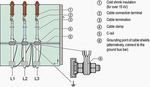
Siemens metal clad switchgear SIMOSEC - Cable connection in cable panel

Siemens metal clad switchgear SIMOSEC - Cable connection in cable panel


The switchgear may now be connected up and cable joints made. In particular one must confirm that the earthing of the switchgear has been carried out using the recommended cross-section of material and satisfactory terminations. The LV system must then be proved for continuity, preferably by using a hand generator or other portable device and with a current of about 1.5 times the design current.

A further examination of all incoming and outgoing circuit and auxiliary cables, including a test of the correctness of the connections at the remote ends, should be done; this should include measuring the insulation resistance and continuity of all cables and wiring including internal and auxiliary connections. Where appropriate, phase rotation checks must be made before three-phase drives are energised. All moving parts must be inspected to ensure they are all operative. Dashpots must be filled to the correct level with the right grade of fluid, and the operation and accuracy of meters and relays by secondary or primary injection tests should be checked.

All settings should be agreed with the client’s engineers.

All cable boxes must be properly topped up and compound filling spouts capped off. All insulators and spouts must be clean and dry and cover plates securely bolted up with all screws in position and tightened and breather vents clear of obstruction. Ensure that the top of the switchgear is free from all dirt and rubbish.

A final check on all incoming and outgoing cable connections to terminals ensures that they are tight and have adequate clearance. High voltage testing can then be carried out to the test figures laid down in the appropriate BS switchgear specification or as specified by the client’s engineers who should witness the tests and sign the test results.

After testing, precautions must be taken to discharge any static and remove the test connections before bolting up any covers removed for testing. Before energising, the operation of all circuit breakers and relays should be confirmed manually and electrically to ensure that no sticking or malfunction is present, particular attention being given to manual trip and close operations and to the operation of overcurrent relays and residual current devices.

Going Alive

When the switchgear is ready to make alive all circuits not in service shall be locked off at each end and safety operation procedures adopted.

All switching operations should be carried out by a competent person.

1 The substation’s entry and emergency exist doors must be operative and kept clear and free from obstruction.

2 All substations should be kept locked when the switchgear is live, and access restricted to authorised personnel only.

3 Danger, safety, shock cards and any statutory notices must be prominently displayed.

4 Tools required for operating switchgear should be stored adjacent to the equipment in proper racks or cabinets.

5 Circuit and interlock keys should also be contained in special cabinets under the control of authorised personnel and no spare keys must be allowed to abort the safety of the system.

6 Batteries should be examined to ensure that they have received their first charge and the electrolyte is at the correct level and of appropriate specific gravity.

7 The fire-fighting requirement should be checked and if it is CO2 it must be confirmed that the safety lock-off procedure is understood by the personnel authorised to enter the substation.

8 External warning notices must be fixed to protect any strangers from inadvertently suffocating.

Reference: Geoffrey Stokes – Handbook of electrical practice

Inspection and Test Procedures for LV Cables

$
0
0
Inspection and Test Procedures for LV Cables

Inspection and Test Procedures for LV Cables

Content

  1. Visual and Mechanical Inspection
  2. Electrical Tests
  3. Test Values
  4. TABLE 100.12 – US Standard Fasteners – Bolt-Torque Values for Electrical Connections

Cables, Low-Voltage, 600 Volt Maximum

1. Visual and Mechanical Inspection

  1. Compare cable data with drawings and specifications.
  2. Inspect exposed sections of cables for physical damage and correct connection in accordance with single-line diagram.
  3. Inspect bolted electrical connections for high resistance using one of the following methods:
    1. Use of low-resistance ohmmeter in accordance with previous Section 1.2.
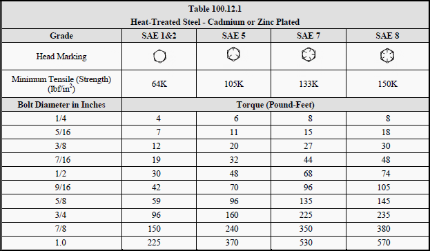
    2. Verify tightness of accessible bolted electrical connections by calibrated torque-wrench method in accordance with manufacturer’s published data or Table 100.12.
    3. Perform thermographic survey:
    • Perform thermographic survey when load is applied to the system
    • Remove all necessary covers prior to thermographic inspection. Use appropriate caution, safety devices, and personal protective equipment
    • Perform a follow-up thermographic survey within 12 months of final acceptance by the owner
  4. Inspect compression-applied connectors for correct cable match and indentation.
  5. Inspect for correct identification and arrangements.
  6. Inspect jacket insulation and condition.
  7. Go to Content ↑


    2. Electrical Tests

    1. Perform resistance measurements through bolted connections with low-resistance ohmmeter.
    2. Perform insulation-resistance test on each conductor with respect to ground and adjacent conductors. Applied potential shall be 500 volts DC for 300 volt rated cable and 1000 volts DC for 600 volt rated cable. Test duration shall be one minute.
    3. Perform continuity tests to insure correct cable connection.
    4. Verify uniform resistance of parallel conductors.

    Go to Content ↑


    3. Test Values

    1. Compare bolted connection resistances to values of similar connections.
    2. Bolt-torque levels should be in accordance with Table 100.12 unless otherwise specified by the manufacturer.
    3. Microhm or millivolt drop values shall not exceed the high levels of the normal range as indicated in the manufacturer’s published data. If manufacturer’s datais not available, investigate any values which deviate from similar connections by more than 50 percent of the lowest value.
    4. Insulation-resistance values should not be less than 50 megohms.
    5. Investigate deviations in resistance between parallel conductors.

    Go to Content ↑

    TABLE 100.12

    US Standard Fasteners – Bolt-Torque Values for Electrical Connections

    Table 100.12.1 - Heat-Treated Steel - Cadmium or Zinc Plated

    Table 100.12.1 - Heat-Treated Steel - Cadmium or Zinc Plated


    Table 100.12.2 - Silicon Bronze Fasteners

    Table 100.12.2 - Silicon Bronze Fasteners


    Table 100.12.3 - Aluminum Alloy Fasteners

    Table 100.12.3 - Aluminum Alloy Fasteners


    Table 100.12.4 - Stainless Steel Fasteners

    Table 100.12.4 - Stainless Steel Fasteners


    a. Consult manufacturer for equipment supplied with metric fasteners.
    b. This table is based on bronze alloy bolts having a minimum tensile strength of 70,000 pounds per square inch.
    c. This table is based on aluminum alloy bolts having a minimum tensile strength of 55,000 pounds per square inch.
    d. This table is to be used for the following hardware types:

    • Bolts, cap screws, nuts, flat washers, locknuts (18–8 alloy)
    • Belleville washers (302 alloy).

    Go to Content ↑

    Resource: Acceptance Testing Specifications for Electrical Power Distribution Equipment and Systems – NETA 2003

    Inspection and Test Procedures for Metal-Enclosed Busways

    $
    0
    0
    Inspection and Test Procedures for Metal-Enclosed Busways

    Inspection and Test Procedures for Metal-Enclosed Busways

    Content

    1. Visual and Mechanical Inspection
    2. Electrical Tests
    3. Test Values
      1. Test Values – Visual and Mechanical
      2. Test Values – Electrical
    4. Tables:
      1. TABLE 100.12 – US Standard Fasteners Bolt-Torque Values for Electrical Connections
      2. TABLE 100.1 – Insulation Resistance Test Values Electrical Apparatus and Systems
      3. TABLE 100.17 – Dielectric Withstand Test Voltages for Metal-Enclosed Bus

    1. Visual and Mechanical Inspection

    1. Compare equipment nameplate datawith drawings and specifications.

    2. Inspect physical and mechanical condition of busway system

    3. Inspect anchorage, alignment, and grounding.

    4. Verify correct connection in accordance with single-line diagram.

    5. Inspect bolted electrical connections for high resistance using one or more of the following methods:

    • Use of a low-resistance ohmmeter in accordance with Section 2 (Electrical Tests).
    • Verify tightness of accessible bolted electrical connections and bus joints by calibrated torque-wrench method in accordance with manufacturer’s published data or Table 100.12 below.
    • Perform thermographic survey
      (NOTE: Remove all necessary covers prior to thermographic inspection. Use appropriate caution, safety devices, and personal protective equipment.)

    6. Confirm physical orientation in accordance with manufacturer’s labels to insure adequate cooling.

    7. Examine outdoor busway for removal of “weep-hole” plugs, if applicable, and the correct installation of joint shield.

    Go to Content ↑


    2. Electrical Tests

    1. Perform resistance measurements through bolted connections and busjoints with a low-resistance ohmmeter, if applicable, in accordance with Section 1 (Visual and Mechanical Inspection).

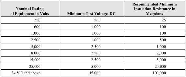
    2. Measure insulation resistance of each busway, phase-to-phase and phase-to-ground for one minute, in accordance with Table 100.1 below.

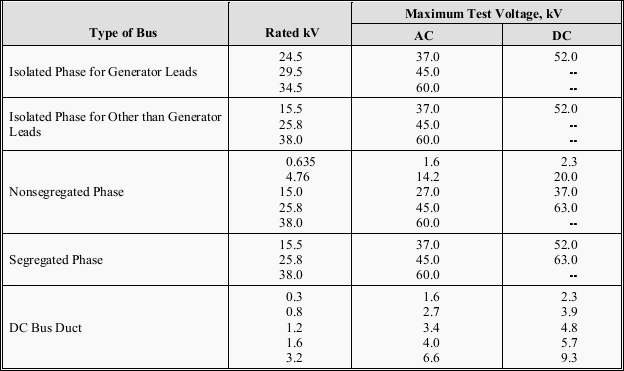
    3. Perform a dielectric withstand voltage test on each busway, phase-to-ground with phases not under test grounded, in accordance with manufacturer’s published data. In the absence of manufacturer’s published data, use Table 100.17.

    Where no dc test value is shown in Table 100.17, ac value shall be used. The test voltage shall be applied for one minute.

    4. Perform a contact-resistance test on each connection point of uninsulated busway. On insulated busway, measure resistance of assembled busway sections and compare values with adjacent phases.

    5. Perform phasing test on each busway tie section energized by separate sources. Tests must be performed from their permanent sources.

    6. Verify operation of busway space heaters.

    Go to Content ↑


    3. Test Values

    3.1 Test Values – Visual and Mechanical

    1. Compare bolted connection resistance values to values of similar connections. Investigate values which deviate from those of similar bolted connections by more than 50 percent of the lowest value. (7.4.1.5.1)

    2. Bolt-torque levels should be in accordance withmanufacturer’s published data. In the absence of manufacturer’s published data, use Table 100.12. (7.4.1.5.2)

    3. Results of the thermographic survey shall be in accordance with Section 9. (7.4.1.5.3)

    Go to Content ↑


    3.2 Test Values – Electrical

    1. Compare bolted connection resistance values to values of similar connections. Investigate values which deviate from those of similar bolted connections by more than 50 percent of the lowest value.

    2. Insulation-resistance test voltages and resistance values shall be in accordance with manufacturer’s published. In the absence of manufacturer’spublished data, use Table 100.1.

    Minimum resistance values are for a nominal 1000-foot busway run. Use the following formula to convert the measured resistance value to the 1000-foot nominal value:

    Busway run - minimum resistance formula

    Converted values of insulation resistance less than those in Table 100.1 or manufacturer’s minimum should be investigated. Dielectric withstand voltage tests shall not proceed until insulation-resistance levels are raised above minimum values.

    3. If no evidence of distress or insulation failure is observed by the end of the total time of voltage application during the dielectric withstand test, the test specimen is considered to have passed the test.

    4. Microhm or dc millivolt drop values shall not exceed the high levels of the normal range as indicated in the manufacturer’s published data.

    If manufacturer’s published data is not available, investigate values which deviate from those of similar bus connections and sections by more than 50 percent of the lowest value.

    5. Phasing test results shall indicate the phase relationships are in accordance with system design.

    6. Heaters shall be operational.

    Go to Content ↑


    TABLE 100.12

    US Standard Fasteners – Bolt-Torque Values for Electrical Connections

    Table 100.12.1 - Heat-Treated Steel - Cadmium or Zinc Plated

    Table 100.12.1 - Heat-Treated Steel - Cadmium or Zinc Plated


    Table 100.12.2 - Silicon Bronze Fasteners

    Table 100.12.2 - Silicon Bronze Fasteners


    Table 100.12.3 - Aluminum Alloy Fasteners

    Table 100.12.3 - Aluminum Alloy Fasteners


    Table 100.12.4 - Stainless Steel Fasteners

    Table 100.12.4 - Stainless Steel Fasteners


    a. Consult manufacturer for equipment supplied with metric fasteners.
    b. This table is based on bronze alloy bolts having a minimum tensile strength of 70,000 pounds per square inch.
    c. This table is based on aluminum alloy bolts having a minimum tensile strength of 55,000 pounds per square inch.
    d. This table is to be used for the following hardware types:

    • Bolts, cap screws, nuts, flat washers, locknuts (18–8 alloy)
    • Belleville washers (302 alloy).

    Go to Content ↑


    TABLE 100.1

    Insulation Resistance Test Values Electrical Apparatus and Systems

    Insulation Resistance Test Values

    Table 100.1 - Insulation Resistance Test Values for Electrical Apparatus and Systems


    Go to Content ↑


    TABLE 100.17

    Dielectric Withstand Test Voltages for Metal-Enclosed Bus

    Dielectric Withstand Test Voltages for Metal-Enclosed Bus

    Table 100.17 - Dielectric Withstand Test Voltages for Metal-Enclosed Bus


    Go to Content ↑

    Resource: Acceptance Testing Specifications for Electrical Power Distribution Equipment and Systems – NETA 2003

    Transformer Routine Test – Measurement of Winding Resistance

    $
    0
    0
    BEST Transformers - OSB Power Transformers Test Laboratory

    BEST Transformers - OSB Power Transformers Test Laboratory

    Calculating Load Loss Values

    Measurement is made to check transformer windings and terminal connections and also both to use as reference for future measurements and to calculate the load loss values at reference (e.g. 75ºC) temperature.

    Measuring the winding resistance is done by using DC current and is very much dependent on temperature.

    Temperature correction is made according to the equations below:

    Temperature correction formulas for copper and aluminium windings

    R2 – winding resistance at temperature t2,
    R1 – winding resistance at temperature t1

    Because of this, temperatures must be measured when measuring the winding resistances and temperature during measurement should be recorded as well.

    Winding resistances are measured between all connection terminals of windings and at all tap positions. During this, winding temperature should also be appropriately measured and recorded.

    The measuring current can be obtained either from a battery or from a constant (stable) current source. The measuring current value should be high enough to obtain a correct and precise measurement and small enough not to change the winding temperature.

    In practice, this value should be larger than 1,2 x I0 and smaller than 0,1 x IN, if possible.

    A transformer consists of a resistance R and an inductance L connected in serial. If a voltage U is applied to this circuit;

    The value of current measurement will be :

    Value of current measurement

    Here, the time coefficient depends on L/R ratio.

    As the measurement current increases, the core will be saturated and inductance will decrease. In this way, the current will reach the saturation value in a shorter time.

    After the current is applied to the circuit, it should be waited until the current becomes stationary (complete saturation) before taking measurements, otherwise, there will be measurement errors.


    Measuring circuit and performing the measurement

    The transformer winding resistances can be measured either by current-voltage method or bridge method. If digital measuring instruments are used, the measurement accuracy will be higher.

    Measuring by the current-voltage method is shown in figure 1 below:

    Measuring the resistance by Current-Voltage method

    Figure 1 - Measuring the resistance by Current-Voltage method


    In the current – voltage method, the measuring current passing through the winding also passes through a standard resistor with a known value and the voltage drop values on both resistors (winding resistance and standard resistance) are compared to find the unknown resistance (winding resistance).

    One should be careful not to keep the voltage measuring voltmeter connected to the circuit to protect it from high voltages which may occur during switching the current circuit on and off.

    The bridge method is based on comparing an unknown (being measured) resistor with a known value resistor.

    When the currents flowing in the arms are balanced, the current through the galvanometer will be zero. In general, if the small value resistors (e.g. less than ≤1 ohm) are measured with a Kelvin bridge and higher value resistors are measured with a Wheatstone bridge, measurement errors will be minimised.

    Kelvin bridge; Wheatstone bridge

    Figure 2 (left) - Kelvin bridge; Figure 3 (right) - Wheatstone bridge


    The resistance measured with the Kelvin Bridge:

    Resistance measured with the Kelvin Bridge

    The resistance measured with the Wheatstone Bridge:

    Resistance measured with the Wheatstone Bridge


    BEST Transformers laboratory

    BEST Transformers - OSB Laboratory

    BEST Transformers - OSB Laboratory


    BEST Test laboratory is equipped with the most advanced testing facilities and is capable of conducting all tests required by IEC standards except short circuit mechanical withstand test, conducted in an independent international laboratory, CESI-Italy.

    Tests performed on the transformers can be classified as follows:

    Tests during manufacturing, routine tests, type tests, special tests, acceptance tests, site tests, defect analysis / identification and tests before maintenance.

    Resource: BEST Transformer – Tests (BALIKESİR ELEKTROMEKANİK SANAYİ TESİSLERİ A.Ş.)

    Testing and Commissioning of Substation DC System

    $
    0
    0
    Testing and Commissioning of Substation DC System

    Testing and Commissioning of Substation DC System (on photo: The battery assembly rated at 108V 200AH, 55 Tungstone Plante Cells all fitted with Aquagen catalytic recombination fillers, which effectively reduce topping up to less than once a year.- by prepair.co.uk)

    Objective

    Power substation DC system consists of battery charger and battery. This is to verify the condition of battery and battery charger and commissioning of them.


    Test Instruments Required

    Following instruments will be used for testing:

    1. Multimeter. (Learn how to use it)
    2. Battery loading unit (Torkel-720 (Programma Make) or equivalent.
      The Torkel-720is capable of providing a constant current load to the battery under test.

      Torkel 720 Battery Load Capacity Tester Front View

      Torkel 720 Battery Load Capacity Tester Front View


    Commissionig Test Procedure

    1. Battery Charger

    1. Visual Inspection: The battery charger cleanliness to be verified. Proper cable termination of incoming AC cable and the outgoing DC cable and the cable connection between battery and charger to be ensured. A stable incoming AC supply to the battery charger is also to be ensured.
    2. Voltage levels in the Float charge mode and the Boost charge mode to be set according to specifications using potentiometer provided.
    3. Battery low voltage, Mains ‘Off”, charger ‘Off’ etc., conditions are simulated and checked for proper alarm / indication. Thus functional correctness of the battery charger is ensued.
    4. Charger put in Commissioning mode for duration specified only one time during initial commissioning of the batteries. (By means of enabling switch.)
    5. Battery charger put in fast charging boost mode and battery set boost charged for the duration specified by the battery manufacturer.
    6. After the boost charging duration, the battery charger is to be put in float charging (trickle charge) mode for continuous operation.
      Some chargers automatically switch to float charge mode after the charging current reduces below a certain value.
    7. Voltage and current values are recorded during the boost charging and float-charging mode.
    NiCad Batteries being regenerated

    NiCad Batteries being charged


    This test establishes the correct operation of the battery charger within the specified voltage and current levels in various operational modes.

    Calculate size of battery bank and inverter – Get MS Excel Spreadsheet!

    2. Battery Unit

    1. Mandatory Condition: The battery set should have been properly charged as per the commissioning instructions of the battery manufacturer for the duration specified.
    2. Visual Inspection: Cleanliness of battery is checked and the electrolyte level checked as specified on the individual cells. The tightness of cell connections on individual terminals should be ensured.
    3. The load current, minimum voltage of battery system, ampere-hour, duration etc., is preset in the test equipment using the keypad.
      For (e.g.) a 58 AH battery set, 5 Hr. duration specification 11.6 A and 5 Hr. duration are set. Minimum voltage setting is = No. of cells x end cell voltage of cells as per manufacturer specification.
    4. It is to be ensured that the set value of the current and duration is within the discharge capacity of the type of cell used. Also the total power to be dissipated in the load unit should be within the power rating of the battery load kit.
    5. Individual cell voltages to be recorded before the start of the test.
    6. Battery charger to be switched off/load MCB in charger to be switched off.
    7. Loading of the battery to be started at the specified current value.
      Individual cell voltages of the battery set are to be recorded every half an hour.
    8. It is to be ensured that all the cell voltages are above the end-cell voltage specified by the manufacturer.
      If any of the cell voltages falls below the threshold level specified by the manufacturer, this cell number is to be noted and the cell needs to be replaced.
    9. Test set automatically stops loading after set duration (or) when minimum voltage reached for the battery set.
    10. Test to be continued until the battery delivers the total AH capacity it is designed for.
      Value of AH and individual cell voltages to be recorded every half an hour.

    Acceptance Limits

    This test establishes the AH capacity of battery set at required voltage.

    The acceptance limit for the test is to ensure the battery set is capable of supplying the required current at specified DC voltage without breakdown for the required duration.

    Resource: Procedures for Testing and Commissioning of Electrical Equipment – Schnedeider Electric

    Testing and Commissioning of MV/HV Cables

    $
    0
    0
    Testing and Commissioning of MV/HV Cables

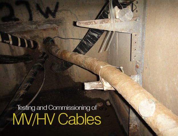
    Example of asbestos paper insulation wrap on high-voltage cable inside an underground cable vault. Several layers of the soft and friable insulation are wrapped around the cable in long, wide strips. Originally, pure white, the discoloration is from sediment mud after formerly being submerged in the once flooded vault; some water leakage is still present.

    1. Visual and Mechanical Inspection

    1. Compare cable data with drawings and specifications.
    2. Inspect exposed sections of cables for physical damage.
    3. Inspect bolted electrical connections for high resistance using one or more of the following methods:
      1. Use of a low-resistance ohmmeter in accordance with Section 1.2 above.
      2. Verify tightness of accessible bolted electrical connections by calibrated torque-wrench method in accordance with manufacturer’s published data or Table 100.12.
      3. Perform a thermographic survey.
        (NOTE: Remove all necessary covers prior to thermographic inspection. Use appropriate caution, safety devices, and personal protective equipment.)
    4. Inspect compression-applied connectors for correct cable match and indentation.
    5. Inspect shield grounding, cablesupports, and terminations.
    6. Verify that visible cable bends meet or exceed ICEA and manufacturer’s minimum published bending radius.
    7. Inspect fireproofing in common cable areas. (**)
    8. If cables are terminated through window-type current transformers, inspect to verify that neutral and ground conductors are correctly placed and that shields are correctly terminated for operation of protective devices.
    9. Inspect for correct identification and arrangements.
    10. Inspect cable jacket and insulation condition.

    ** Optional test

    2. Electrical Tests

    1. Perform resistance measurements through bolted connections with a low-resistance ohmmeter, if applicable, in accordance with Section 1.1.
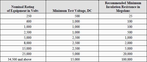
    2. Perform an insulation-resistance test individually on each conductor with all other conductors and shields grounded. Apply voltage in accordance with manufacturer’s published data. In the absence of manufacturer’s published data, use Table 100.1.
    3. Perform a shield-continuity test on each power cable.
    4. In accordance with ICEA, IEC, IEEE and other power cable consensus standards, testing can be performed by means of direct current, power frequency alternating current, or very low frequency alternating current. These sources may be used to perform insulation-withstand tests, and baseline diagnostic tests suchas partial discharge analysis, and power factor or dissipation factor. The selection shall be made after an evaluation of the available test methods and a review of the installed cable system.
      .
      Some ofthe available test methods are listed below:
      .
      1. Dielectric Withstand:
        1. Direct current (DC) dielectric withstand voltage
        2. Very low frequency (VLF) dielectric withstand voltage
        3. Power frequency (50/60 Hz) dielectric withstand voltage
      2. Baseline Diagnostic Tests:
        1. Power factor/ dissipation factor (tan delta):
          1. Power frequency (50/60 Hz)
          2. Very low frequency (VLF)
        2. DC insulation resistance:
        3. Off-line partial discharge:
          1. Power frequency (50/60 Hz)
          2. Very low frequency (VLF)

    3. Test Values

    3.1 Test Values – Visual and Mechanical

    1. Compare bolted connection resistance values to values of similar connections. Investigate values which deviate from those of similar bolted connections by more than 50 percent of the lowest value.
    2. Bolt-torque levels should be in accordance with manufacturer’s published data. In the absence of manufacturer’s published data, use Table 100.12.
    3. Results of the thermographic survey.
      (NOTE: Remove all necessary covers prior to thermographic inspection. Use appropriate caution, safety devices, and personal protective equipment.)
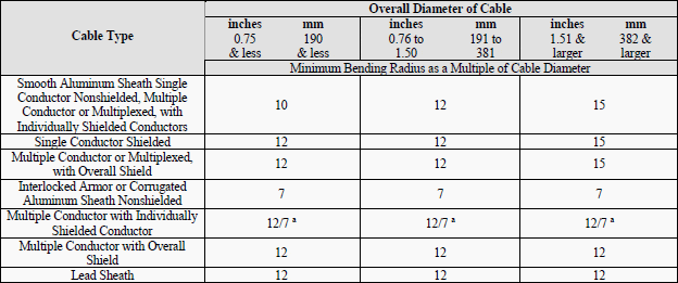
    4. The minimum bend radius to which insulated cables may be bent for permanent training shall be in accordance with Table 100.22.

    3.2 Test Values – Electrical

    1. Compare bolted connection resistance values to values of similar connections. Investigate values which deviate from those of similar bolted connections by more than 50 percent of the lowest value.
    2. Insulation-resistance values shall be in accordance with manufacturer’s published data. In the absence of manufacturer’s published data, use Table 100.1.Values of insulation resistance less than this table or manufacturer’s recommendations should be investigated.
    3. Shielding shall exhibit continuity. Investigate resistance values in excess of ten ohms per 1000 feet of cable.
    4. If no evidence of distress or insulation failure is observed by the end of the total time of voltage application during the dielectric withstand test, the test specimen is considered to have passed the test.
    5. Based on the test methodology chosen, refer to applicable standards or manufacturer’s literature for acceptable values.

    Tables

    Table 100.12.1

    Bolt-Torque Values for Electrical Connections

    - US Standard Fasteners (a)
    - Heat-Treated Steel – Cadmium or Zinc Plated (b)

    Bolt-Torque Values for Electrical Connections

    Table 100.12.1 - Bolt-Torque Values for Electrical Connections


    a) Consult manufacturer for equipment supplied with metric fasteners.
    b) Table is based on national coarse thread pitch.


    Table 100.12.2

    - US Standard Fasteners (a)
    - Silicon Bronze Fasteners (b, c)

    Torque (Pound-Feet)

    Torque (Pound-Feet)

    Torque (Pound-Feet)


    a) Consult manufacturer for equipment supplied with metric fasteners.
    b) Table is based on national coarse thread pitch.
    c) This table is based on bronze alloy bolts having a minimum tensile strength of 70,000 pounds per square inch.


    Table 100.12.3

    - US Standard Fasteners (a)
    - Aluminum Alloy Fasteners (b, c)

    Torque (Pound-Feet)

    Torque (Pound-Feet) - Aluminum Alloy Fasteners

    Torque (Pound-Feet) - Aluminum Alloy Fasteners


    a) Consult manufacturer for equipment supplied with metric fasteners.
    b) Table is based on national coarse thread pitch.
    c) This table is based on aluminum alloy bolts having a minimum tensile strength of 55,000 pounds per
    square inch.


    Table 100.12.4

    - US Standard Fasteners (a)
    - Stainless Steel Fasteners (b, c)

    Torque (Pound-Feet)

    Torque (Pound-Feet) - Stainless Steel Fasteners

    Torque (Pound-Feet) - Stainless Steel Fasteners


    a) Consult manufacturer for equipment supplied with metric fasteners.
    b) Table is based on national coarse thread pitch.
    c) This table is to be used for the following hardware types:

    • Bolts, cap screws, nuts, flat washers, locknuts (18-8 alloy)
    • Belleville washers (302 alloy).

    Tables in 100.12 are compiled from Penn-Union Catalogue and Square D Company, Anderson Products Division, General Catalog: Class 3910 Distribution Technical Data, Class 3930 Reference Data Substation Connector Products.


    Table 100.1

    Insulation Resistance Test Values Electrical Apparatus and Systems

    Insulation Resistance Test Values Electrical Apparatus and Systems

    Table 100.1 - Insulation Resistance Test Values Electrical Apparatus and Systems


    In the absence of consensus standards dealing with insulation-resistance tests, the Standards Review Council suggests the above representative values. Test results are dependent on the temperature of the insulating material and the humidity of the surrounding environment at the time of the test.

    Insulation-resistance test data may be used to establish a trending pattern. Deviations from the baseline information permit evaluation of the insulation.


    Table 100.22

    Minimum Radii for Power Cable

    Single and Multiple Conductor Cables with Interlocked Armor, Smooth or Corrugated Aluminum Sheath or Lead Sheath

    Minimum Radii for Power Cable

    Table 100.22 - Minimum Radii for Power Cable


    ANSI/ICEA S-93-639/NEMA WC 74-2000, 5-46 kV Shielded Power Cable for Use in the Transmission and Distribution of Electric Energy, Appendix I – Recommended Bending Radii for Cables and Table I1 – Minimum Radii for Power Cable.

    a. 12 x individual shielded conductor diameter, or 7 x overall cable diameter, whichever is greater.

    Resource: STANDARD FOR ACCEPTANCE TESTING SPECIFICATIONS for Electrical Power Equipment and Systems (NETA 2009)

    Transformer Routine Test – Measurement Of No-Load Loss And Current

    $
    0
    0
    Transformer Routine Test - Measurement Of No-Load Loss And Current

    Transformer Routine Test - Measurement Of No-Load Loss And Current (on photo: Power transformer - BEST)

    Introduction to test

    The no-load losses are very much related to the operational performance of a transformer. As long as the transformer is operated, these losses occur. For this reason, no load losses are very important for operational economy. No-load losses are also used in the heating test.

    The no-load loss and current measurements of a transformer are made while one of the windings (usually the HV winding) is kept open and the other winding is supplied at the rated voltage and frequency.

    During this test the no-load current (Io) and the no-load losses (Po) are measured.

    The measured losses depend heavily on the applied voltage waveform and frequency. For this reason, the waveform of the voltage should be very sinusoidal and at rated frequency.

    Normally, the measurements are made while the supply voltage is increased at equal intervals from 90% to 115% of the transformer rated voltage (Un) and this way the values at the rated voltage can also be found.


    No-load losses and currents

    The no-load losses of a transformer are grouped in three main topics:

    1. Iron losses at the core of the transformer,
    2. Dielectric losses at the insulating material and
    3. The copper losses due to no-load current.

    The last two of them are very small in value and can be ignored.

    So, only the iron losses are considered in determining the no-load losses.


    Measuring circuit and performing the measurement

    Connection diagram for measuring no-load losses

    Connection diagram for measuring no-load losses


    In general according to the standards, if there is less than 3% difference between the effective (U) value and the average (U’) value of the supply voltage, the shape of the wave is considered as appropriate for measurements.

    If the supply voltage is different than sinusoid, the measured no-load losses have to be corrected by a calculation. In this case, the effective (r.m.s.) value and the average (mean) value of the voltage are different. If the readings of both voltmeter are equal, there is no need for correction.

    During measurements, the supply voltage U´ is supplied to the transformer by the average value voltmeter. In this way, the foreseen induction is formed and as a result of this, the hysteresis losses are measured correctly. The eddy-current losses should be corrected according to equation below.

    Pm = P0 · (P1 + k · P2)

    Pm: Measured loss
    P0: No-load losses where the voltage is sinusoidal

    Here: P0 = Ph + PE = k1 · f + k2 · f2

    k = [ U / U' ]2

    P1: The hysteresis loss ratio in total losses (Ph) = k1 · f
    P2: The eddy-curent loss ratio in total losses (PE) = k2 · f2

    At 50 Hz and 60 Hz, in cold oriented sheet steel, P1 = P2 = % 50. So, the P0 no-load loss becomes:

    Po = Pm / (P1 + k · P2)   where P1 = P2 = 0,5

    According to IEC 60076-1: Pm = P0 · (1 + d)   where d = [ (U' - U) / U' ]

    During no-load loss measurement, the effective value of the no-load current of the transformer is measured as well. In general, in three phase transformers, evaluation is made according to the average of the three phase currents.

    Before the no-load measurements, the transformer might have been magnetised by direct current and it’s components (resistance measurement or impulse tests).

    For this reason, the core has to be demagnetised. To do this, it has to be supplied by a voltage value (increasing and decreasing between the maximum and minimum voltage values for a few minutes) higher than the rated voltage for a certain time and then the measurements can be made.

    The no-load currents are neither symmetrical nor of equal amplitude in three phase transformers. The phase angles between voltages and currents may be different for each of three phases.

    For this reason, the wattmeter readings on each of the three phases may not be equal. Sometimes one of the wattmeter values can be 0 (zero) or negative (-).

    Resource: Transformer Tests – BEST Transformers

    Transformer Routine Test – Measurement of Voltage Ratio and Check of Phase Displacement

    $
    0
    0
    Transformer Routine Test – Measurement of Voltage Ratio and Check of Phase Displacement

    Transformer Routine Test – Measurement of Voltage Ratio and Check of Phase Displacement (on photo: OSB laboratory of BEST Transformers)

    Introduction

    The no-load voltage ratio between two windings of a transformer is called turn ratio.

    The aim of measurement is: Confirming the no-load voltage ratio given in the customer order specifications, determining the conditions of both the windings and the connections and examining the problems (if any).

    The measurements are made at all tap positions and all phases.


    Measurement circuit and performing the measurement

    1. Turn Ratio Measurement

    The turn ratio measurement can be made using two different methods:

    1. Bridge method
    2. By measuring the voltage ratios of the windings

    1. Bridge method

    Measurement of turn ratio is based on, applying a phase voltage to one of the windings using a bridge (equipment) and measuring the ratio of the induced voltage at the bridge.

    The measurements are repeated in all phases and at all tap positions, sequentially.

    During measurement, only turn ratio between the winding couples which have the same magnetic flux can be measured, which means the turn ratio between the winding couples which have the parallel vectors in the vector diagram can be measured. (Figures 2.1, 2.2, 2.3).

    In general, the measuring voltage is 220 V a.c. 50 Hz. However, equipment which have other voltage levels can also be used. The accuracy of the measuring instrument is ≤ ±0,1%.

    Bridge connection for measuring the turn ratio

    Figure 1-1 - Bridge connection for measuring the turn ratio


    1 - Transformer under test
    2 – Transformer with adjustable range (standard)
    3 – Zero position indicator
    U1 – Applied voltage to the bridge and HV winding (220 V, 50 Hz)
    U2 – Induced voltage at the LV winding

    Theoretical turn ratio = HV winding voltage / LV winding voltage

    The theoretical no-load turn ratio of the transformer is adjusted on the equipment by an adjustable transformer, it is changed until a balance occurs on the % error indicator.

    The value read on this error indicator shows the deviaton of the transformer from real turn ratio as %.

    Deviaton of the transformer from real turn ratio


    2. By measuring the voltage ratios of the windings

    The voltages at the winding couples to be measured, can be measured at the same time and the ratio can be determined, or digital instruments which are manufactured for this purpose can be used in the voltage ratio measurement method.

    By using such instruments, in addition to measuring the turn ratio, also determining the connection group (with three phase measuring instrument) and measuring the currents during measurement are also possible.

    The method of comparing the vector couple voltages also allows measuring the angle (phase slip) between vectors at the same time.


    2. Determining the Connection Group

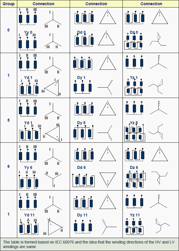
    Depending on the type of the transformer, the input and output windings of a multi-phase transformer are connected either as star ( Y ) or delta ( D ) or zigzag ( Z ). The phase angle between the high voltage and the low voltage windings varies between 0° and 360° .

    Representing as vectors, the HV winding is represented as 12 (0) hour and the other windings of the connection group are represented by other numbers of the clock in reference to the real or virtual point.

    For example, in Dyn 11 connection group the HV winding is delta and the LV winding is star and there is a phase difference of 330° (11×30°) between two windings. While the HV end shows 12 (0), the LV end shows 11 o’clock (after 330°).

    Determining the connection (vector) group is valid only in three phase transformers. The high voltage winding is shown first (as reference) and the other windings follow it.

    If the vector directions of the connection are correct, the bridge can be balanced.

    Also, checking the connection group or polarity is possible by using a voltmeter. Direct current or alternating current can be used for this check. The connections about the alternating current method are detailed in standards. An example of this method is shown on a vector diagram below.

    The no-load deviation of the turn ratios should be ≤ % 0,5 .

    Figure 1-2 - Connection group representation and measuring

    Figure 1-2 - Connection group representation and measuring


    The order of the measurements:

    1) 3 phase voltage is applied to ABC phases
    2) Voltage between phases (e.g. AC) is measured
    3) A short circuit is made between C and n
    4) Voltage between B and b’ is measured
    5) Voltage between A and c’ is measured

    As seen from the vector diagram, in order to be Dyn 11 group , A.c’ > AB > B.b’ correlation has to realized.

    Taking the other phases as reference for starting, same principles can be used and also for determining the other connection groups, same principles will be helpful.

    Some of the connection groups according to IEC 60076-1 standard

    Figure 2.3 - Some of the connection groups according to IEC 60076-1 standard


    Resource: BEST Transformer – Tests (BALIKESİR ELEKTROMEKANİK SANAYİ TESİSLERİ A.Ş.)


    Defining Size and Location of Capacitor in Electrical System (1)

    $
    0
    0
    Defining Size and Location of Capacitor in Electrical System (1)

    Defining Size and Location of Capacitor in Electrical System (1)

    Content

    1. Fixed type capacitor banks
    2. Automatic type capacitor banks
    3. Types of APFC – Automatic Power Factor Correction
  8. Type of Capacitor as per Construction
  9. Selecting Size of Capacitor Bank
  10. Selection of Capacitor as per Non Liner Load
  11. Configuration of Capacitor:
    1. Star-Solidly Grounded
    2. Star-Ungrounded
    3. Delta-connected Banks
  12. Effect of series and Parallel Connection of capacitor:
    1. Parallel Connection
    2. Series Connection

    Type of Capacitor Bank as per Its Application

    1. Fixed type capacitor banks

    The reactive power supplied by the fixed capacitor bank is constant irrespective of any variations in the power factor and the load of the receivers. These capacitor banks are switched on either manually (circuit breaker / switch) or semi automatically by a remote-controlled contactor.

    This arrangement uses one or more capacitor to provide a constant level of compensation.

    These capacitors are applied at the terminals of inductive loads (mainly motors), at bus bars.

    Disadvantages:

    • Manual ON/OFF operation.
    • Not meet the require kvar under varying loads.
    • Penalty by electricity authority.
    • Power factor also varies as a function of the load requirements so it is difficult to maintain a consistent power factor by use of Fixed Compensation i.e. fixed capacitors.
    • Fixed Capacitor may provide leading power factor under light load conditions, Due to this result in overvoltages, saturation of transformers, mal-operation of diesel generating sets, penalties by electric supply authorities.

    Application:

    • Where the load factor is reasonably constant.
    • Electrical installations with constant load operating 24 hours a day
    • Reactive compensation of transformers.
    • Individual compensation of motors.
    • Where the kvar rating of the capacitors is less than, or equal to 15% of the supply transformer rating, a fixed value of compensation is appropriate.
    • Size of Fixed Capacitor bank Qc 15% kVA transformer

    Go to Content ↑


    2. Automatic type capacitor banks

    The reactive power supplied by the capacitor bank can be adjusted according to variations in the power factor and the load of the receivers.

    These capacitor banks are made up of a combination of capacitor steps (step = capacitor + contactor) connected in parallel. Switching on and off of all or part of the capacitor bank is controlled by an integrated power factor controller.

    The equipment is applied at points in an installation where the active-power or reactive power variations are relatively large, for example:

    • At the bus bars of a main distribution switch-board,
    • At the terminals of a heavily-loaded feeder cable.

    Where the kvar rating of the capacitors is less than, or equal to 15% of the supply transformer rating, a fixed value of compensation is appropriate.

    Above the 15% level, it is advisable to install an automatically-controlled bank of capacitors.

    Control is usually provided by contactors. For compensation of highly fluctuating loads, fast and highly repetitive connection of capacitors is necessary, and static switches must be used.

    Go to Content ↑


    Types of APFC – Automatic Power Factor Correction

    Automatic Power Factor correction equipment is divided into three major categories:

    1. Standard = Capacitor + Fuse + Contactor + Controller
    2. De tuned = Capacitor + De tuning Reactor + Fuse + Contactor + Controller
    3. Filtered = Capacitor + Filter Reactor + Fuse + Contactor + Controller.

    Advantages:

    • Consistently high power factor under fluctuating loads.
    • Prevention of leading power factor.
    • Eliminate power factor penalty.
    • Lower energy consumption by reducing losses.
    • Continuously sense and monitor load.
    • Automatically switch on/off relevant capacitors steps for consistent power factor.
    • Ensures easy user interface.
    • Automatically variation, without manual intervention, the compensation to suit the load requirements.

    Application:

    • Variable load electrical installations.
    • Compensation of main LV distribution boards or major outgoing lines.
    • Above the 15% level, it is advisable to install an automatically-controlled bank of capacitors.
    • Size of Automatic Capacitor bank Qc > 15% kVA transformer.
    MethodAdvantagesDisadvantages
    Individual capacitorsMost technically efficient, most flexibleHigher installation & maintenance cost
    Fixed bankMost economical, fewer installationsLess flexible, requires switches and/or circuit breakers
    Automatic bankBest for variable loads, prevents over voltages, low installation costHigher equipment cost
    CombinationMost practical for larger numbers of motorsLeast flexible

    Go to Content ↑


    Type of Capacitor as per Construction

    1. Standard duty Capacitor

    Construction: Rectangular and Cylindrical (Resin filled / Resin coated-Dry)

    Application:

    1. Steady inductive load.
    2. Non linear up to 10%.
    3. For Agriculture duty.

    2. Heavy-duty

    Construction: Rectangular and Cylindrical (Resin filled / Resin coated-Dry/oil/gas)

    Application:

    1. Suitable for fluctuating load.
    2. Non linear up to 20%.
    3. Suitable for APFC Panel.
    4. Harmonic filtering

    3. LT Capacitor

    Application:

    • Suitable for fluctuating load.
    • Non linear up to 20%.
    • Suitable for APFC Panel & Harmonic filter application.

    Go to Content ↑


    Selecting Size of Capacitor Bank

    The size of the inductive load is large enough to select the minimum size of capacitors that is practical.

    For HT capacitors the minimum ratings that are practical are as follows:

    System VoltageMinimum rating of capacitor bank
    3.3 KV , 6.6KV75 Kvar
    11 KV200 Kvar
    22 KV400 Kvar
    33 KV600 Kvar

    Unit sizes lower than above is not practical and economical to manufacture.

    When capacitors are connected directly across motors it must be ensured that the rated current of the capacitor bank should not exceed 90% of the no-load current of the motor to avoid self-excitation of the motor and also over compensation.

    Precaution must be taken to ensure the live parts of the equipment to be compensated should not be handled for 10 minutes (in case of HT equipment) after disconnection of supply.

    Crane motors or like, where the motors can be rotated by mechanical load and motors with electrical braking systems, should never be compensated by capacitors directly across motor terminals.

    For direct compensation across transformers the capacitor rating should not exceed 90 % of the no-load KVA of the motor.

    Go to Content ↑


    Selection of Capacitor as per Non Liner Load

    For power Factor correction it is need to first decide which type of capacitor is used.

    Selection of Capacitor is depending upon many factor i.e. operating life, Number of Operation, Peak Inrush current withstand capacity.

    For selection of Capacitor we have to calculate Total Non-Liner Load like: UPS, Rectifier, Arc/Induction Furnace, AC/DC Drives, Computer, CFL Blubs, and CNC Machines.
    • Calculation of Non liner Load, Example: Transformer Rating 1MVA,Non Liner Load 100KVA
    • % of non Liner Load = (Non Liner Load/Transformer Capacity) x100 = (100/1000) x100=10%.
    • According to Non Linear Load Select Capacitor as per Following Table.
    % Non Liner LoadType of Capacitor
    <=10%Standard Duty
    Up to 15%Heavy Duty
    Up to 20%Super Heavy Duty
    Up to 25%Capacitor +Reactor (Detuned)
    Above 30%

    Go to Content ↑


    Configuration of Capacitor

    Power factor correction capacitor banks can be configured in the following ways:

    1. Delta connected Bank.
    2. Star-Solidly Grounded Bank.
    3. Star-Ungrounded Bank.

    Go to Content ↑


    1. Star-Solidly Grounded

    • Initial cost of the bank may be lower since the neutral does not have to be insulated from ground.
    • Capacitor switch recovery voltages are reduced
    • High inrush currents may occur in the station ground system.
    • The grounded-Star arrangement provides a low-impedance fault path which may require revision to the existing system ground protection scheme.
    • Typically not applied to ungrounded systems. When applied to resistance-grounded systems, difficulty in coordination between capacitor fuses and upstream ground protection relays (consider coordination of 40 A fuses with a 400 A grounded system).
    • Application: Typical for smaller installations (since auxiliary equipment is not required)

    Go to Content ↑


    2. Star-Ungrounded

    Industrial and commercial capacitor banks are normally connected ungrounded Star, with paralleled units to make up the total kvar.

    It is recommended that a minimum of 4 paralleled units to be applied to limit the over voltage on the remaining units when one is removed from the circuit.

    If only one unit is needed to make the total kvar, the units in the other phases will not be overloaded if it fails.

    In industrial or commercial power systems the capacitors are not grounded for a variety of reasons. Industrial systems are often resistance grounded. A grounded Star connection on the capacitor bank would provide a path for zero sequence currents and the possibility of a false operation of ground fault relays.

    Also, the protective relay scheme would be sensitive to system line-to-ground voltage Unbalance, which could also result in false relay tripping.

    Application: In Industrial and Commercial.

    Go to Content ↑


    3. Delta-connected Banks

    Delta-connected banks are generally used only at distributions voltages and are configured with a Single series group of capacitors rated at line-to-line voltage. With only one series group of units no overvoltage occurs across the remaining capacitor units from the isolation of a faulted capacitor unit.

    Therefore, unbalance detection is not required for protection and they are not treated further in this paper.

    Application: In Distribution System.

    Go to Content ↑


    Effect of series and Parallel Connection of capacitor

    Parallel Connection

    This is the most popular method of connection. The capacitor is connected in parallel to the unit. The voltage rating of the capacitor is usually the same as or a little higher than the system voltage.

    Go to Content ↑


    Series Connection

    This method of connection is not much common. Even though the voltage regulation is much high in this method,

    It has many disadvantages.

    One is that because of the series connection, in a short circuit condition the capacitor should be able to withstand the high current. The other is that due to the series connection due to the inductivity of the line there can be a resonance occurring at a certain capacitive value.

    This will lead to very low impedance and may cause very high currents to flow through the lines.

    Go to Content ↑

    Erection procedure for HV switchgear (Part 1)

    $
    0
    0
    Erection procedure for HV switchgear

    Erection procedure for HV switchgear (on photo: 150KV GI Electrical Substation extension in Greece, Atherinolakos Crete by PARALOS Engineering S.A.)

    Important points

    66kV/230kV GIS extension work

    66kV/230kV GIS extension work (photo by Rotary Switchgear & Testing Pte. Ltd)

    Before commencing erection of HV switchgear check that all connections are tight on busbars and on main circuits as well as auxiliary circuits.

    Examine the insulation very carefully, because there have been reported cases of burned out connections due to failure to observe this precaution. Obvious faults such as distorted panel work, broken meter glass and damaged packing cases should be noted and immediate steps taken to rectify the damage or to return the equipment to the supplier or manufacturer.

    After erection, steps must be taken to prevent deterioration of the equipment due to damp, dust or casual damage. Substations should be cleared out and locked fast and should not be used as a site office, store or workshop after the equipment has been installed.

    When all erection and jointing work is complete the equipment must be inspected and thoroughly cleaned to remove cuttings of cable, spare nuts, washers, accumulations of dust or copper filings and tools which may have been left behind.

    However, it is dangerous to blow out equipment because dust, filings, light metal scraps, rags and sawdust can be blown into positions where they become inaccessible and may pass unnoticed. It is better to clean manually and vacuum the plant.

    An important point to remember is the removal of all packing materials particularly in moving parts, and of course make sure that oil circuit-breakers receive their first filling of water-free oil.

    In the erection of the switchgear the following points should be emphasised.

    Where steel channels are used as foundations, ensure that they are correctly laid to an accuracy of about ±1mm in 3 m. Use a masking strip to prevent fouling by the floor materials.

    IMPORTANT: Read and apply the manufacturer’s erection instructions and use the correct tools such as torque spanners to obtain the appropriate tightness of nuts.

    GIS Installation (photo by Rotary Switchgear & Testing Pte. Ltd)

    GIS Installation (photo by Rotary Switchgear & Testing Pte. Ltd)


    Make sure equipment is properly aligned. This means vertically and horizontally in both longitudinal and lateral directions. Incorrect alignment causes problems during operation of mechanical linkages and connections, difficulty in removing and replacing circuit-breakers and other withdrawable parts and puts stress on interpanel connections such as busbars and earth bars.

    When the floor is being laid and there are no steel inset channels, it should be level both front to back and should not vary by more than a millimetre or so between cubicle centres.

    When the floor is being laid it is common practice to form pockets at the foundation hole positions in order to avoid having to cut them out of the solid floor at installation time. The floor should be marked out in accordance with the switchgear assembly drawings usually provided by the manufacturer to ensure that the switchgear is correctly located with respect to cable trenches, building walls and other equipment in the room.

    A datum line requires to be established usually along the rear foundation bolts, and using normal geometric methods the switchboard and foundation bolt holes can be located.

    The method of positioning the equipment is dependent on a number of factors such as equipment size, building location, site accessibility and lifting tackle available.

    Lifting eyes are often either incorporated into switchboards or can be screwed into pre-machined holes, but generally slinging is necessary and this should be done strictly in accordance with the manufacturer’s recommendations. Without the use of cranes, however, the traditional manual methods utilising jacks and roller bars are effective.

    Care must be taken not to exert pressure on weak parts such as control handles during this manhandling.


    Instalation of GIS and Erection of GIB (VIDEO)

    Cant see this video? Click here to watch it on Youtube.

    Will be continued soon…

    Resource: Handbook of Electrical Installation Practice – Eur Ing Geoffrey Stokes (Get it from Amazon)
    Erection procedure for HV switchgear (Part 2)

    $
    0
    0
    ABB Gas-insulated Switchgear ELK-04 Modular System up to 170 kV, 4000 A, 63 kA

    ABB Gas-insulated Switchgear ELK-04 Modular System up to 170 kV, 4000 A, 63 kA


    Continued from first part: Erection procedure for HV switchgear (Part 1)


    Positioning of cubicles

    Positioning of the cubicles should start near to the centre of the switchboard, installing as early as possible the enclosures associated with any special chambers or trunking.

    The first enclosure should be positioned and checked to ensure the side sheets are plumb and that any runner rails are level in both planes.

    When the first enclosure panel is correctly set the remaining enclosures should be positioned successively on alternate sides of this panel to make the front form an unbroken line.

    Adjacent enclosures should be bolted together after they have been correctly aligned using whatever shimming proves necessary to make sure that the cubicles are vertically and horizontally true. The fixing bolts should be positioned in the foundation holes and cemented in leaving adequate time for the cement to set before tightening up.

    The equipment may now be connected up and cable joints made.

    In particular one must confirm that the earthing of the equipment has been carried out using the recommended cross-section of material and satisfactory terminations.

    The LV system must then be proved for continuity, preferably by using a hand generator or other portable device and with a current of about 1.5 times the design current. A further examination of all incoming and outgoing circuit and auxiliary cables, including a test of the correctness of the connections at the remote ends, should be done; this should include measuring the insulation resistance and continuity of all cables and wiring including internal and auxiliary connections.

    Where appropriate, phase rotation checks must be made before three-phase drives are energised.

    All moving parts must be inspected to ensure they are all operative.

    Dashpots must be filled to the correct level with the right grade of fluid, and the operation and accuracy of meters and relays by secondary or primary injection tests should be checked. All settings should be agreed with the client’s engineers.

    Gas-insulated switchgear ELK-04 with integrated control cabinets

    Gas-insulated switchgear ELK-04 with integrated control cabinets


    All cable boxes must be properly topped up and compound filling spouts capped off. All insulators and spouts must be clean and dry and cover plates securely bolted up with all screws in position and tightened and breather vents clear of obstruction. Ensure that the top of the equipment is free from all dirt and rubbish.

    A final check on all incoming and outgoing cable connections to terminals ensures that they are tight and have adequate clearance. High-voltage testing can then be carried out to the test figures laid down in the appropriate switchgear specification or as specified by the client’s engineers who should witness the tests and sign the test results.

    After testing, precautions must be taken to discharge any static and remove the test connections before bolting up any covers removed for testing.

    Before energising, the operation of all circuit-breakers and relays should be confirmed manually and electrically to ensure that no sticking or malfunction is present, particular attention being given to manual trip and close operations and to the operation of overcurrent relays and residual current devices.

    When the equipment is ready to make alive all circuits not in service shall be locked off at each end and safety operation procedures adopted. All switching operations should be carried out by a competent person.

    The substation’s entry and emergency exist doors must be operative and kept clear and free from obstruction. All substations should be kept locked when the equipment is live, and access restricted to authorised personnel only.

    Danger, safety, shock cards and any statutory notices must be prominently displayed.

    Tools required for operating switchgear should be stored adjacent to the equipment in proper racks or cabinets. Circuit and interlock keys should also be contained in special cabinets under the control of authorised personnel and no spare keys must be allowed to abort the safety of the system. Batteries should be examined to ensure that they have received their first charge and the electrolyte is at the correct level and of appropriate specific gravity.

    The fire-fighting requirement should be checked and if it is CO2 it must be confirmed that the safety lock-off procedure is understood by the personnel authorised to enter the substation.

    External warning notices must be fixed to protect any strangers from inadvertently suffocating.


    Prefabricated gas-insulated switchgear (GIS)

    Integrated GIS is a prefabricated gas-insulated switchgear (GIS) unit with housing is based on ABB’s well-proven GIS technology and can be produced at the same speed as a conventional GIS but has a considerably shorter installation time which is less than 50 percent of typical GIS installations.

    Cant see this video? Click here to watch it on Youtube.

    Resource: Handbook of Electrical Installation Practice – Eur Ing Geoffrey Stokes (Get it from Amazon)

    When a transformer has stomach pain and wants to…

    $
    0
    0
    Transformer windings forces due to the magnetic forces

    Transformer windings forces due to the magnetic forces (photo by ALSTOM)

    About stomach pain

    During normal operation, transformer internal structures and windings are subjected to mechanical forces due to the magnetic forces. These forces are illustrated in Figure 1.

    By designing the internal structure very strong to withstand these forces over a long period of time, service life can be extended. However, in a large transformer during a “through fault” (fault current passing through a transformer), forces can reach millions of pounds, pulling the coils up and down and pulling them apart 60/50 times per second.

    Notice in Figure 1 that the internal low-voltage coil is being pulled downward, while the high-voltage winding is pulled up, in the opposite direction.

    At the same time, the right-hand part of the figure shows that the high- and low-voltage coils are being forced apart.

    Transformer Internal Forces

    Figure 1 - Transformer Internal Forces


    Keep in mind that these forces are reversing 50/60 times each second. It is obvious why internal structures of transformers must be built incredibly strong.

    Many times, if fault currents are high, these forces can rip a transformer apart and cause electrical faults inside the transformer itself. This normally results in arcing inside the transformer that can result in explosive failure of the tank, throwing flaming oil over a wide area.

    There are protective relaying systems to protect against this possibility, although explosive failures do occur occasionally.


    How to prevent pain

    Through Fault – Short Circuit withstand considerations

    The windings are subject to both radial and axial forces related to the current and flux interactions. Radial forces in the inner winding (normally the LV winding) are in compression while the outer winding (normally the HV winding) forces are in tension.

    Design of the windings and bracing must consider the magnitude of these forces and provide adequate strength to withstand them without significant mechanical deformation which could result in a dielectric failure.

    The picture below is an example ofa free bucking mechanical failure of an inner winding resulting from radial forces in compression on the winding. Note, even though there is mechanical failure, there wasn’t a dielectric failure of this winding.

    Free bucking mechanical failure of an inner winding

    Free bucking mechanical failure of an inner winding resulting from radial forces in compression on the winding


    Flux fields are dependent of the balance of the ampere turn distribution of the HV and LV windings. When the ampere turns of the HV and LV windings are equal and balanced, the only forces are radial.

    DETC taps (De Energized Tap Changer) in the HV windings and LTC (Load Tap Changer) operation result in changes in the ampere turn distribution resulting in axial forces. If the HV and LV windings are not aligned axially or one winding is physically shorter than the other, ampere turn balance is significantly affected and axial forces are magnified.

    Transfomer core force and flux

    Transfomer core force and flux


    Autotransformers, low impedance, motor starting duty, transformers with multiple voltages by reconnecting the transformer windings in series and parallel configurations, three winding transformers with dual secondary windings for start up or unit auxiliary service at power plants – all can result in increased axial and radial forces during a short circuit and require special consideration.


    Construction of power transformer (VIDEO)

    Cant see this video? Click here to watch it on Youtube.


    Primary and assembly process (VIDEO)

    Cant see this video? Click here to watch it on Youtube.

    References:
    • Transformers Basics, Maintenance and Diagnostics – U.S. Dpt. of the Interior Bureau of Reclamation
    • The Design and Performance of Circular Disc, Helical and Layer Windings for Power Transformer Applications - David L. Harris, P.E.

    Erection Procedure for Power Transformer

    $
    0
    0
    Erection of power transformer

    Erection of power transformer (by Entel Energoprojekt in Abu Dhabi Distribution Company, 33KV & 11KV Network for Ghuzlan Island)


    This technical article deals with transformers and their installation so we restrict ourselves here to the procedures associated with their commissioning. Transformers should be inspected for internal or external damage, particularly if they have been dropped or tipped over.

    This should include such items as:

    1. Drain valves, selector switches,
    2. Conservator tanks,
    3. Buchholz relays and
    4. Winding temperature indicators.

    All transformers must be tested for winding insulation resistance and the readings confirmed as acceptable.

    However HV D.C. tests on a cable connected transformer cannot be done because the windings of the transformer short out the d.c test set.

    If between-core tests are required on transformer feeder cables after installation then a link box must be provided to disconnect the cable from the transformer windings. If transformer covers are taken off to achieve internal disconnection the tools used must be clean and secured externally by white tape so that they may be recovered if inadvertently dropped.

    All nuts and washers must be accounted for and all operatives should be asked to empty their pockets while working over the open tank.

    Waterproof covers should be provided during the period when the transformer tank is open. If it is not possible to disconnect the cables after jointing they must be tested beforehand. This means that the jointing and testing programme must be carefully planned to avoid leaving cable ends unsealed for long periods.

    Transformer diagrams should be inspected and the phasing diagram confirmed as correct. Also before energising, the voltage selector must be set on the appropriate tapping having regard to the voltage level of the system.

    Transformers which are to operate in parallel must be set on the same tapping and they should be checked as having the same impedance. Voltage selectors should be locked in their set position and if they are of the ‘off-circuit’ type they must not be adjusted without the supply being first switched off. Earthing arrangements for the tank and the neutral or other system earthing must be confirmed and completed before testing and commissioning.

    Where special tests for losses, ratio, phase angle or winding resistances are specified the assistance of the manufacturer should be sought.

    The following points should be checked on the particular type of transformer as appropriate:


    Oil immersed naturally cooled (ON)

    Erection of oil immersed transformer

    Erection of oil immersed transformer


    Ensure that the oil level is adequate and that breather tubes are clear. Commission silica gel units by removing the airtight seals from the cannisters and filling the oil sealing-well to the correct level with transformer oil.

    The colour of the silica gel must be checked and the filling changed if it shows dampness (red for wet, blue for dry).


    Dry-type transformers

    Erection of dry-type power transformer

    Erection of dry-type power transformer


    As dry-type transformers are more susceptible to external damage they must be carefully handled and stored on site.

    They must also be kept in a dry, warm atmosphere until they are put in service, to prevent ingress of moisture.

    Satisfactory insulation tests are imperative before commissioning. Because they are wholly dependent on surface radiation and air convection for cooling, they must be checked for any accumulation of dust or dirt which can block the air ducts and reduce the flow of air. Cleanliness is essential, particularly where the connection leads leave the windings and at the terminal supports. Damp dust leads to tracking and causes expensive damage.

    It is particularly important to check such transformers for dust in package substations which may escape the notice of commissioning staff.

    Resource: Handbook of Electrical Installation Practice – Eur Ing Geoffrey Stokes (Get it from Amazon)

    Transformer Routine Dielectric (Insulation) Test

    $
    0
    0
    Transformer Routine Dielectric (Insulation) Test

    Transformer Routine Dielectric (Insulation) Test (on photo: OSB laboratory of BEST Transformers)

    Insulation tests to be performed

    The following insulation tests are performed in order to meet the transformer insulation strength expectations. Unless otherwise requested by the customer, the following test are performed in the following order (IEC 60076-3) :

    1. Switching impulse test:

    To confirm the insulation of the transformer terminals and windings to the earthed parts and other windings, and to confirm the insulation strength in the windings and through the windings.

    2. Lightning impulse test

    to confirm the transformer insulation strength in case of a lightning hitting the connection terminals.

    3. Separate source AC withstand voltage test

    To confirm the insulation strength of the transformer line and neutral connection terminals and the connected windings to the earthed parts and other windings.

    4. Induced AC voltage test (short duration ACSD and long duration ACLD)

    To confirm the insulation strength of the transformer connection terminals and the connected windings to the earthed parts and other windings, both between the phases and through the winding.

    5. Partial discharge measurement

    To confirm the “partial dicharge below a determined level” property of the transformer insulationstructure under operating conditions.

    According to standards, the transformer windings are made to meet the maximum operating voltage Um and the related insulation levels.

    The transformer insulation levels and the insulation test to be applied according to IEC 60076-3 is shown in the below table.

    Winding
    structure
    Maximum operating
    voltage
    Um kV
    Tests
    Lightning
    impulse
    (LI)
    Switching
    impulse
    (SI)
    Long
    duration AC
    (ACLD)
    Short
    duration AC
    (ACSD)
    Applied
    voltage test
    uniform
    insulated
    Um ≤ 72,5type
    (note 1)
    nana
    (note 1)
    routineroutine
    uniform
    and
    gradually
    insulated
    72,5 < Um ≤ 170routinenaspecialroutineroutine
    170 < Um ≤ 300routineroutine
    (note 2)
    routinespecial
    (note 2)
    routine
    ≥ 300routineroutineroutinespecialroutine
    Note 1: In some countries, in transformers with Um ≤ 72,5 kV applied as routine test and the ACLD test is applied as routine or type test.

    Note 2 : If the ACSD test is defined, the SI test is not applied.

    In case of a transformer with one or more thanone gradual insulation, if foreseen by the induced voltage test, the switching impulse test isdetermined according to the maximum Um voltage winding.

    The foreseen test voltage can not be reached in lower Um voltage windings. In this case, the ratio between the tap changer’s optimum tap position and the windings shall be such arranged that, the lowest Um voltage winding reaches the most appropriate value. This is acceptable (IEC 60076-3).

    If chopped wave is requested during ligthning impulse (LI) test, the peak value of the chopped wave is 1.1 times the full wave value (10% higher). For transformers with the high voltage winding Um> 72.5 kV, the lightning impulse (LI) test is a routine test for all windings of the transformer.


    Repeating the dielectric tests

    If no modification is made in the internal insulation of a transformer, only maintenance is made, or if insulation tests are required for a transformer which is in operation, and if no agreement is made with the customer, test is performed with test voltages at 80% of the original test values. However, the long duration induced voltage test (ACLD) is always repeated with 100% of the original value.

    For new transformers with factory tests completed, tests are repeated always with 100% of the original values.

    Resource: BEST Transformer – Tests (BALIKESİR ELEKTROMEKANİK SANAYİ TESİSLERİ A.Ş.)

    Condition Monitoring of Transformers

    $
    0
    0
    Condition Monitoring of Transformers

    Condition Monitoring of Transformers (on photo: distributive tranformer; by Gazoogleheimer via Flickr )

    Detecting early signs of deterioration

    It is possible to provide transformers with measuring devices to detect early signs of degradation in various components and provide warning to the operator in order to avoid a lengthy and expensive outage due to failure.

    The technique, which can be applied to other plant as well as transformers, is called condition monitoring, as the intent is to provide the operator with regular information on the condition of the transformer.

    By reviewing the trends in the information provided, the operator can make a better judgement as to the frequency of maintenance, and detect early signs of deterioration that, if ignored, would lead to an internal fault occurring.

    Such techniques are an enhancement to, but are not a replacement for, the protection applied to a transformer.

    The extent to which condition monitoring is applied to transformers on a system will depend on many factors, amongst which will be the policy of the asset owner, the suitability of the design (existing transformers may require modifications involving a period out of service – this may be costly and not justified), the importance of the asset to system operation, and the general record of reliability.

    Therefore, it should not be expected that all transformers would be, or need to be, so fitted.

    A typical condition monitoring system for an oil immersed transformer is capable of monitoring the condition of various transformer components (bushings, tank, tap changer, coolers and conservators) as shown in Table 1 below.

    Condition monitoring for transformers

    Table 1 - condition monitoring for transformers


    There can be some overlap with the measurements available from a digital/numerical relay.

    By the use of software to store and perform trend analysis of the measured data, the operator can be presented with information on the state of health of the transformer, and alarms raised when measured values exceed appropriate limits. This will normally provide the operator with early warning of degradation within one or more components of the transformer, enabling maintenance to be scheduled to correct the problem prior to failure occurring.

    The maintenance can obviously be planned to suit system conditions, provided the rate of degradation is not excessive.

    As asset owners become more conscious of the costs of an unplanned outage, and electric supply networks are utilised closer to capacity for long periods of time, the usefulness of this technique can be expected to grow.

    Reference: Network Protection & Automation Guide – Areva


    High voltage testing – Direct current (DC)

    $
    0
    0
    High voltage testing - Direct current (DC)

    High voltage testing - Direct current (DC) - Photo by www.powertechlabs.com

    DC Tests

    DC tests are used mainly to do pressure tests” on high voltage cables. Although the cables operate with AC, AC testing is not practical.

    The high capacitance of the cables necessitates AC test sets with a high kVA rating to be able to supply the capacitive current. In the case of DC, once the cable is charged, only the losses have to be supplied.

    DC test sets usually consist of half wave rectification, using HV selenium rectifiers.

    Typical DC test set-up is shown in Figure 1.

    Typical circuit for DC tests

    Figure 1 - Typical circuit for DC tests


    An AC high voltage test transformer is again supplied via a variac and a rectifier is used together with a filter capacitor C to limit the ripple to acceptable values. The earthing switch ES is a safety feature and closes automatically when the power is switched off to discharge the capacitor C.

    Note that the peak inverse voltage required of the rectifier is 2 Vm.

    Typical doubling circuit for DC tests

    Figure 2 - Typical doubling circuit for DC tests


    Doubling and multiplier circuits (as used in TV’s and household appliances) are also used to obtain an even higher voltage. A typical Cockcroft-Walton (in Germany: Greinacher) doubling circuit is shown in Figure 2.

    Typical waveforms and a typical doubling circuit DC test source

    Figure 3 - Typical waveforms and a typical doubling circuit DC test source


    Resource: High Voltage Engineering Practice and Theory – Dr JP Holtzhausen; Dr WL Vosloo

    Commissioning of HV Panel – Operational and Functional Checkup

    $
    0
    0
    Commissioning of HV Panel - Operational and Functional Checkup

    Commissioning of HV Panel - Operational and Functional Checkup (on photo Macmillan – New High Voltage Panel by Skilz Building Solutions)

    Main Objective

    The main objective of the test is to check the proper operation function of the circuit breaker; in this test we do the following:


    A. Close Operation Test – Local—Remote

    This test is conducted by manual, Local and Remote.

    For the manual Operation test, we will charge the spring manual and breaker is also closed my manual and opening also done. For the Local operation we give Control supply and A.C supply for spring charge motor.

    We close the Circuit Breaker using the TNC (Trip Neutral Control) switch.

    We observe for the closing coil function and spring charging of motor operation. For remote operating is the site is ready (such as plc or BMS) then remote operation is done using the remote system.

    If its site is not ready for this, we provide a local signal to the remote terminal and observe the operation of breaker.


    B. Trip Operation Test – Local-Remote

    This test is conducted by manual, Local and Remote. For the manual Operation test, The manually charged breaker is opened using the Trip switch.. For the Local operation we give Control supply and A.C supply for spring charge motor. We open the Breaker using the TNC switch.

    We observe for the tripping coil function. For remote operating is the site is ready (such as plc or BMS) then remote operation is done using the remote system.

    If its site is not ready for this, we provide a local signal to the remote terminal and observe the operation of breaker.


    C. Protection Trip

    For this test the breaker has in closed position at initially. We provide an auxiliary rated voltage to Master trip relay, and observe the opening of the breaker and the position of the trip coil.

    Functional Check

    1. Emergency Trip

    For this test the breaker has to be in charged or ON position, we operate the emergency push button. We observe the operation of circuit breaker opening.


    2. Aux. Switch Operation

    When the breaker is in open condition we check the Aux. contact of the breaker using continuity tester, to conform the contact is in NO /NC. Then we close the Circuit Breaker and check the same contact with continuity tester, to conform the contact is in NC /NO.


    3. On-Off Indications (Lamp + Flag)

    When the breaker is in open condition we check the Lamp + Flag of the relay. Then we close the Circuit Breaker and check the same Lamp operation.


    4. Trip / Trip circuit healthy Lamp Indication

    The relay is operated and we observer the Trip lamp indication.


    5. Limit Switch for spring charge motor

    On this test we observe the operation of the limit switch of the spring charging motor.

    We give an A.C power to motor and observer the operation of motor and charging of spring, on the indication of fully charged spring the motor operation has to get stopped.


    6. Test / Service Limit Switch

    This test is conducted to check the Test / Service Limit Switch Operation. During rack out the Breaker we obverse the indicator to change to test position and during rack in the breaker we obverse the indicator to change to service.

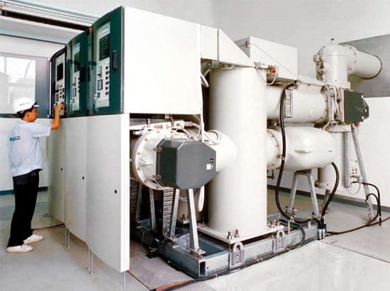

    7. Operation Counter

    This test is conducted if operational counter provision is available in breaker. We operated the breaker and look for the change in counter for counting the operation.


    8. Heater / Heater Switch / Thermostat

    The control A.C supply is given for heater and we look for heater operation.


    9. Function of illumination and socket switch

    In this test we look for the panel internal illumination and socket switch operation. We operate the limit switch manually and observe the operation of illumination circuit.

    Reference: Commissioning of HT electrical system – Sterling & Wilson Ltd.

    Identifying The Primary And Secondary Phasor Polarities Of Transformer – Polarity Test

    $
    0
    0
    CPC 100 - Universal testing device for electrical diagnostics

    CPC 100 - Universal testing device for electrical diagnostics on transformers, current transformers, voltage transformers, grounding systems, lines and cables, and circuit breakers (photo by www.omicron.at)

    Polarity Detection

    This is needed for identifying the primary and secondary phasor polarities. It is a must for poly phase connections. Both a.c. and d.c methods can be used for detecting the polarities of the induced emfs.

    The dot method is used to indicate the polarities.

    The transformer is connected to a low voltage a.c. source with the connections made as shown in the Figure 1 (a). A supply voltage Vs is applied to the primary and the readings of the voltmeters V1, V2 and V3 are noted. V1 : V2 gives the turns ratio.

    If V3 reads V1−V2 then assumed dot locations are correct (for the connection shown).

    Transformer polarity test scheme

    Figure 1 - Transformer polarity test scheme


    The beginning and end of the primary and secondary may then be marked by A1 − A2 and a1 − a2 respectively. If the voltage rises from A1 to A2 in the primary, at any instant it does so from a1 to a2 in the secondary.

    If more secondary terminals are present due to taps taken from the windings they can be labeled as a3, a4, a5, a6. It is the voltage rising from smaller number towards larger ones in each winding. The same thing holds good if more secondaries are present.

    Figure 1 (b) shows the d.c. method of testing the polarity. When the switch S is closed if the secondary voltage shows a positive reading, with a moving coil meter, the assumed polarity is correct. If the meter kicks back the assumed polarity is wrong.

    Reference: Electrical Machines I – Prof. Krishna Vasudevan, Prof. G. Sridhara Rao, Prof. P. Sasidhara Rao

    Testing and Commissioning Procedure For Motors

    $
    0
    0
    Testing and Commissioning Procedure For Motors

    Testing and Commissioning Procedure For Motors // Photo by TECO Middle East (TME)

    Scope Of Motor Testing

    It should be noted that the scope of motor testing depends upon the motor type and size, this being indicated on the inspection forms.

    Motor vibration shall be measured in a tri-axial direction, i.e.:

    • Point x axis – side of bearing housing at shaft height
    • Point y axis – top of bearing housing
    • Point z axis – axial of bearing housing at shaft height
    The measurements shall be carried out with an instrument conforming to ISO 2954 (10-1000 Hz frequency range). With the motor at normal operating temperature, the vibration velocity shall not exceed 2.8 mm/s RMS, or 4 mm/s PEAK, in any direction.

    For bearings fitted with proximity probes, the unfiltered peak-to-peak value of vibration (including shaft ‘run-out) at any load between no load and full load, shall not exceed the following values:

    • 50 µm for two-pole motors
    • 60 µm for four-pole motors
    • 75 µm for six-pole or higher motors
    Motor bearing

    Motor bearing (photo by CCLW INTERNATIONAL)


    Bearing temperature rise limits following a ‘heat run’ of 3.5 – 4 hours are as follows:

    Rolling bearings:

    • Outer ring measurement max. 90 °C
    • Temperature rise from ambient max. 50 °C

    Sleeve bearings:

    • Oil temperature max. 90 °C
    • Bearing temperature rise by RTD max. 50 °C
    • Lub. oil temperature rise from ambient max. 30 °C (for forced lub. oil systems).
    When commissioning or re-commissioning motors, precautions shall be taken to avoid excessive vibration caused by the phenomenon known as ‘soft foot‘; i.e. feet which do not have solid flat contact with the base prior to the tightening of the holding-down bolts.

    This may be measured and rectified during installation or detected during running by the loosening of each holding-down bolt in turn while measuring motor vibration.


    Motor ‘Soft Foot’ Condition

    ‘Soft feet’ are those which do not have solid flat contact with the base prior to the tightening of the holding-down bolts; one or more feet may be ‘soft’ as shown in Figures 1 to 3.

    The profile of the foot contact area may be as shown in Figures 4 to 6.

    The profile of the foot contact area

    The profile of the foot contact area (Figures 1, 2 and 3)


    • Figure 1 - Machine resting on 3 feet, foot 4 is raised or ‘soft’
    • Figure 2 - Machine resting on diagonal formed by feet 3 and 4, feet 1 and 4 are ‘soft’
    • Figure 3 - Bottoms of all 4 feet are not parallel with base, feet 3 and 4 are ‘soft’
    Profile of 'soft foot' contact area

    Profile of 'soft foot' contact area


    NOTE: Re-machining of rotor feet is required in Figures 4 and 5; temporary use of wedge-shaped shims may be acceptable (maintenance).

    Forms

    Form 14 – Inspection of electric motor – Cage-induction type (incl. control unit)

    Inspection of electric motor cage-induction type (including control unit)

    Inspection of electric motor cage-induction type (including control unit)

    Form 4 – Inspection of Switching Units – HV Switchgear

    Inspection of Switching Units - HV Switchgear

    Inspection of Switching Units - HV Switchgear

    Form 11 – Inspection Of Outgoing Unit – LV Switchboard

    Inspection Of Outgoing Unit - LV Switchboard

    Inspection Of Outgoing Unit - LV Switchboard


    Reference: Field Commissioning and Maintenance Of Electrical Installations and Equipment Manual

    8 Important Checks To Do Before Powering Up The Dry-Type Transformer

    $
    0
    0
    8 Important Checks To Do Before Powering Up The Dry-Type Transformer (on photo: TRIHAL transformer by Schneider Electric)

    8 Important Checks To Do Before Powering Up The Dry-Type Transformer (on photo: TRIHAL transformer by Schneider Electric)

    8 Obligatory Checks

    The transformer should be powered up only after checking the following 8 items:

    star 1st Check (name plate ratings)

    Make sure the name plate ratings are in accordance with the ratings foreseen for the place of installation.

    Transformer nameplate with ratings and connections

    Transformer nameplate with ratings and connections

    star 2nd Check (parallel operation)

    When transformers are to be operated in parallel, make sure they are connected with the right polarity. If there is only one transformer or more of them, but not operated in parallel, just skip to the next check.

    Learn more about principles of transformers in parallel connection.

    Parallel connection of transformers

    Parallel connection of transformers

    star 3rd Check (connections: cables, bus bars)

    Make sure all connections to cables or bus bars are properly connected and well positioned.

    Transformer low voltage connections to the busbars CANALIS

    Transformer low voltage connections to the busbars CANALIS

    star 4th Check (tap change connections)

    Make sure that all connections at the tap change panel are firmly tightened and at the same position in the three phases.

    Tap change connections

    Tap change connections

    star 5th Check (grounding connection)

    Make sure the grounding mesh is correctly connected to the bolt provided for this purpose.

    In addition, make sure the grounding mesh has been correctly executed at the right place foreseen in the project and shown in the drawing.

    Earth connection MUST be checked

    Earth connection MUST be checked

    star 6th Check (thermal protective device)

    In case of transformers fitted with a thermal protective device, check the connections of the circuit, making sure that the voltage is in accordance and that the alarm and shut-off contacts are connected to their corresponding loops.

    Transformer thermal protection relay ZIEHL

    Transformer thermal protection relay ZIEHL

    star 7th Check (impurities removal)

    Make sure there are no materials, equipment or any other impurities laid on the transformer, between the coils or obstructing the ventilation in the cooling channels.


    star 8th Check (insulation resistance test)

    It is always recommendable to check the insulation resistance by making measurements between the LV and HV windings and from the windings to the ground.

    Cant see this video? Click here to watch it on Youtube.

    ONLY after these checks are made, the transformer can be connected to the system.

    Voltage shall be applied while the transformer is set to no load, and such voltage shall be measured at the secondary winding to check for the corresponding output ratings. Operations under voltages other than the rated one can cause saturation significant loss increase, which could lead to over-heating and noise above the standard levels.

    Warning! If the transformer is set to an improper tap, noises above the standard levels are to be expected.

    The load should be applied progressively until the rated power .

    References:
    • Schneider Electric – Trihal Catalogue
    • Instruction Manual For Dry-type Transformers – WEG
    Viewing all 158 articles
    Browse latest View live