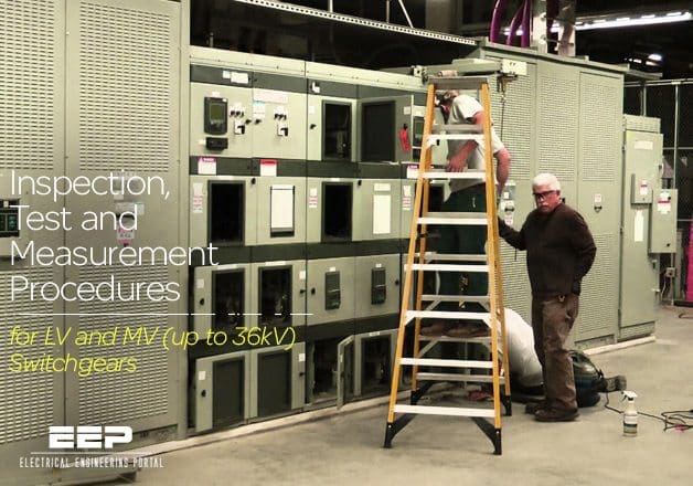
Inspection, Test and Measurement Procedures for LV and MV (up to 36kV) Switchgears (on photo” Eaton Cutler Hammer Magnum DS Switchgear Inspection, and Transformer Testing)
Importance of checks and maintenance
Installed in clean, well ventilated or air-conditioned locations, switchgear will require little routine maintenance.
Major inspection should be scheduled for power plant shutdowns and concentrate for low voltage switchboards on identifying contact wear, correct operation of interlocks, correct overload settings and fuse sizes, signs of overheating, and undue dirt or corrosion. For MV switchgear similar considerations apply although more extensive checks on protective devices, circuit breaker oil, vacuum bottle contact distances are required as specified by the Manufacturer.
Gas Insulated Switchgear (GIS) shall be maintained in accordance with the manufacturer’s recommendations. Where extensive (intrusive) maintenance is required, the Manufacturer should be involved in the activity.
For older switchgear, a condition assessment should be performed to establish that the equipment remains in a suitable condition for further service.
Partial discharge testing and infrared scanning can be used to obtain data on the performance of the insulation system and the integrity of the switchgear busbars and cable terminations. The frequency of such tests will depend on the duty, age and condition of the switchgear.

Infrared partial discharge testing (photo credit: reliabilityweb.com)
NOTE //
The effectiveness of infra-red scanning depends on the ability to access the current-carrying components under loaded condition. Scanning through metallic enclosures has generally proved ineffective. Removal of enclosures of live equipment may not be possible without compromising electrical safety.
LV switchgear
| Type | Description | Interval | Extent |
| 1. INSPECTION | General external condition. | 1 y | All |
| Motor starters and outgoing feeders, internal. Incomers, internal. | 4 y | ||
| Busbar compartments (1). | 8 y | ||
| Metering: - Correctness main voltmeters. - Correctness main ammeters. | 4y | ||
| General internal condition of outdoor equipment (5). | 2 y | ||
| 2. TEST AND MEASUREMENT (3) | Incoming feeders, bus section, switches: - Operating mechanism. - Interlocks. - Control equipment. - Electrical protection/tripping (2). | 4 y | All |
| Busbar systems: - Torque bolts (1). - Insulation resistance. - Continuity (ductor). | 8 y | ||
| Motor feeders: - Draw-out system/interlocks. - Cable connection tightness. | 4 y | ||
| Thermal and earth fault protection. | 4 y | 10% | |
| Certified Ex ‘e’ thermal protection (4). | 3 y | All | |
| Restart system. | 4 y | 10% | |
| Insulation resistance of motor + cable. | 4 y | selected | |
| Plain feeders: - Draw-out system/interlocks. - Cable connection tightness. | 4 y | All | |
| Protection/tripping. (2) | 4 y | 10% | |
| R.C.D. for fixed load (e.g. trace heating). | 4 y | All |
NOTES:
- Access to modern, high integrity, insulated/segregated busbar systems may be difficult. In this case other test and measurements as indicated should give sufficient information on the actual condition.
- CT connected protection relays should be tested by means of secondary injection.
- Testing of change-over systems of emergency switchboards should coincide with the testing of the emergency generator/system.
- Type of protection ‘e’. Motor protection devices are selected so that the tripping time from hot when the locked rotor current of the motor is carried, is carried with the motor in the stalled condition, is less than the time tE on the motor nameplate.
- Internal inspection should be limited to contactor/control equipment installed out of doors in boxes, e.g. MOV control panels.
MV switchgear (up to 36 kV)
| Type | Description | Interval | Extent |
| 1. INSPECTION | General external condition. | 1 y | All |
| Cable boxes internal. Circuit breakers internal. Fused contactors internal. | 4 y | ||
| Busbar compartments (1) internal. | 8 y | ||
| Metering: - Correctness of main voltmeters. - Correctness of main ammeters. - Correctness of other measuring systems. | 4 y | All | |
| 2. TEST AND MEASUREMENT (3) | Circuit breakers in/outgoing and fused contactors (3): - Operating mechanism. - Draw-out system/interlocks. - Control equipment. - Insulation resistance | 4 y | All |
| Dielectric strength across open contacts. | 8 y | ||
| Ductor test across closed contacts. Electrical protection/tripping (2). | 4 y | ||
| Certified Ex’e’ thermal protection (4). | 3 y | ||
| Contact distance. | 4 y | Vacuum, SF6 | |
| Dielectric test oil. | 4 y | Oil-immersed | |
| Insulation resistance of cable (incl. motor if applicable). | 4 y | All | |
| Restart system. | 4 y | Motors | |
| Busbar systems: - Torque bolts (1). - Insulation resistance. - Dielectric strength. - Continuity (ductor). | 8 y | All | |
| Correctness of kW, kVAr, max. demand of measuring systems (5). | 4 y | ||
| 3. RESTORATION | Greasing of operating mechanisms. | 4 y | All |
| Oil filtering/replacement. Component replacement. | As necessary |
NOTES:
- Access to modern, high integrity, insulated/segregated busbar systems may be difficult. In this case other test and measurements as indicated should give sufficient information on the actual condition.
- CT connected protection relays should be tested by means of secondary injection.
- After operation of the circuit breaker/contactor following a short circuit, the proper operation of switching device and its protection shall be tested.
- Type of protection ‘e’.
Motor protection devices are selected so that the tripping time from hot when carrying the locked rotor current of the motor is carried, with the motor in the stalled condition, is less than the stated time tE on the motor nameplate. - Where used for tariff purposes.
Reference: Field commissioning and maintenance of electrical installations and equipment // DEP 63.10.08.11-Gen.