Test On 110kV Power Cable After Installation (Part 3)
General description of site test procedure
In previous two parts of this technical article first six procedures were explained. Now the last three (7, 8 and 9) will be explained in details:
- Phase indication test (part 1)
- DC conductor resistance measurement (part 1)
- Capacitance test (par 1)
- DC Sheath test on outher sheath (part 2)
- Insulation resistance measurement (part 2)
- Cross bonding check (part 2)
- Zero sequence and positive sequence impedance test
- Earth resistance measurement at link boxes
- Link box contact resistance measurement
7. Zero sequence and positive sequence impedance test
Positive sequence impedance are calculated assuming that there are no metallic elements that are placed within an influential distances of cable (Railway lines, pipe lines or buried equipment’s etc.).
The presence of other metals or metallic objects influences the sequence impedance. Because of influence of other unknown factors, it is recommended that the impedance should be measured in the field after the circuits are installed. Positive and negative sequence impedance for cables is same value, because the impedance of these in uncharged if a symmetrical voltage system with reverse sequence is applied to them.
Usually the zero sequence impedance can be assumed as 3 times the positive sequence impedance value as a practice for initial approximation.
The three currents of zero sequence system, equal in magnitude and direction, are opposed by an impedance that is determined by the loops formed by the three cable cores and returned by the metallic sheaths and earth in parallel. The effective AC resistance of the zero sequence system includes both the effective resistance of the line conductor as well as that of earth return.
The zero sequence impedance can be determined by measurement or calculation when the three phase of the system are connected in parallel and single phase AC current is applied to them.
Instruments / Equipment used
- 3-phase variable transformer (up to 100 Amps supply capacity).
- Impedance measurement equipment – Digital.
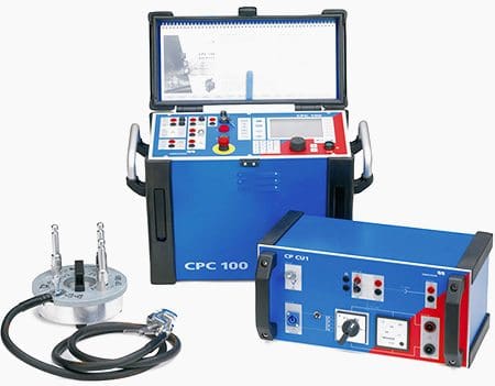
CP-CU1 Omicron for Zero positive sequence test and capacitance measurements
Instructions
Measurement of positive/negative sequence impedance:
- The measurement is done between two phases of the circuit once the complete circuit is installed, cable may be transposed and cross bonded between the terminations. There should be electric accessibility to the cable cores at terminations.
- The connections should be made as per Figure 1A.
- Turn up the power with the variable transformer until 25 Amps of current starts flowing. Switch the impedance measurement equipment and record the voltage, current and angle (power factor).
- Switch off after the measurement and turn the variable transformer down.
- The measurement is to be repeated three times: between R & Y, between R & B and between Y & B phases.
Measurement of zero sequence impedance
- The measurement is done by connecting the three phases of circuit connected in parallel and a single phase AC voltage is applied to them.
- The connections should be made as per Figure 1B.
- Turn up the power with the variable transformer until 25 Amps of current starts flowing. Switch the impedance measurement equipment and record the voltage, current and angle (power factor).
- Switch off after the measurement and turn the variable transformer down.
- Repeat for each phase.
Schematic diagrams

Figure 1A – Schematic layout for measurement of Positive/Negative Sequence Impedance

Figure 1B – Schematic layout for measurement of Zero Sequence Impedance
8. Earth resistance measurement at link boxes
The measurement of earth resistance is mainly intended for the purpose of grounding the links of bonding system of high voltage cable screen.
Equipment / Instruments used
Analogue Earth tester Model-04102A, Make-KYORITSU.
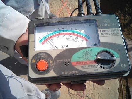
Analogue Earth tester Model-04102A, Make-KYORITSU
Instructions
- Check the battery voltage, set the range switch to battery check position and press test button and make sure the indicator is at right of BATT GOOD position.
- The connections as per the figure bellow.
- Check the earth voltage by setting switch to earth voltage position, make sure the voltage is 10V or less. If the earth voltage is higher, the result may be with excessive high errors.
- Measure the earth resistance by setting the switch to resistance range position and press test button.
- The earth resistance must not exceed 5Ω for outside substation and 3Ω for inside substation.
Schematic diagram
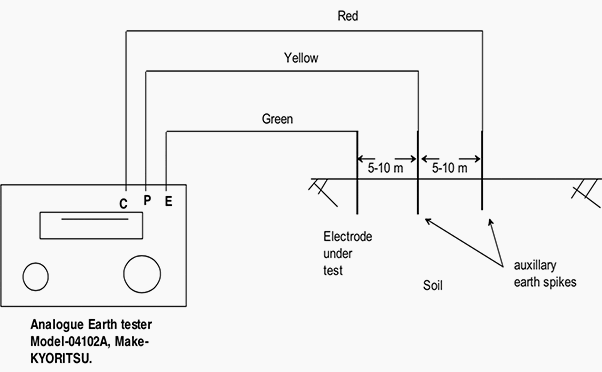
Earth resistance measurement at link boxes
9. Link box contact resistance measurement
This test is basically carried out after installation of link boxes and connecting leads.
Equipment / Instruments used
- Megger DLRO-200 for contact resistance and DC resistance measurements
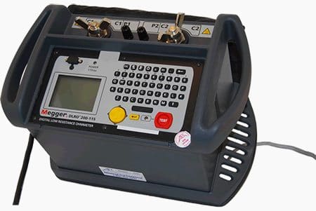
Megger DLRO-200 for contact resistance and dc resistance measurements
Instructions
- All the bolts are to be tightened firmly
- Connect the micro-ohmmeter with the link box as shown in figure below.
- The micro-ohmmeter shall be applied between earth copper bar and each disconnect able copper bars.
- Test shall be repeated for individual connections.
- The values should bein micro-ohm range.
Schematic layout

Link box contact resistance schemetic layout