Transformer Routine Test – Measurement of Voltage Ratio and Check of Phase Displacement (on photo: OSB laboratory of BEST Transformers)
Introduction
The no-load voltage ratio between two windings of a transformer is called turn ratio.
The measurements are made at all tap positions and all phases.
Measurement circuit and performing the measurement
1. Turn Ratio Measurement
The turn ratio measurement can be made using two different methods:
- Bridge method
- By measuring the voltage ratios of the windings
1. Bridge method
Measurement of turn ratio is based on, applying a phase voltage to one of the windings using a bridge (equipment) and measuring the ratio of the induced voltage at the bridge.
The measurements are repeated in all phases and at all tap positions, sequentially.
During measurement, only turn ratio between the winding couples which have the same magnetic flux can be measured, which means the turn ratio between the winding couples which have the parallel vectors in the vector diagram can be measured. (Figures 2.1, 2.2, 2.3).
In general, the measuring voltage is 220 V a.c. 50 Hz. However, equipment which have other voltage levels can also be used. The accuracy of the measuring instrument is ≤ ±0,1%.

Figure 1-1 - Bridge connection for measuring the turn ratio
1 - Transformer under test
2 – Transformer with adjustable range (standard)
3 – Zero position indicator
U1 – Applied voltage to the bridge and HV winding (220 V, 50 Hz)
U2 – Induced voltage at the LV winding
Theoretical turn ratio = HV winding voltage / LV winding voltage
The theoretical no-load turn ratio of the transformer is adjusted on the equipment by an adjustable transformer, it is changed until a balance occurs on the % error indicator.
The value read on this error indicator shows the deviaton of the transformer from real turn ratio as %.

2. By measuring the voltage ratios of the windings
The voltages at the winding couples to be measured, can be measured at the same time and the ratio can be determined, or digital instruments which are manufactured for this purpose can be used in the voltage ratio measurement method.
The method of comparing the vector couple voltages also allows measuring the angle (phase slip) between vectors at the same time.
2. Determining the Connection Group
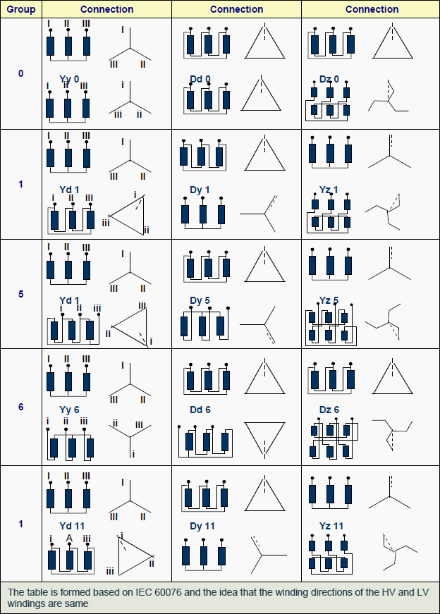
Depending on the type of the transformer, the input and output windings of a multi-phase transformer are connected either as star ( Y ) or delta ( D ) or zigzag ( Z ). The phase angle between the high voltage and the low voltage windings varies between 0° and 360° .
For example, in Dyn 11 connection group the HV winding is delta and the LV winding is star and there is a phase difference of 330° (11×30°) between two windings. While the HV end shows 12 (0), the LV end shows 11 o’clock (after 330°).
Determining the connection (vector) group is valid only in three phase transformers. The high voltage winding is shown first (as reference) and the other windings follow it.
If the vector directions of the connection are correct, the bridge can be balanced.
Also, checking the connection group or polarity is possible by using a voltmeter. Direct current or alternating current can be used for this check. The connections about the alternating current method are detailed in standards. An example of this method is shown on a vector diagram below.
The no-load deviation of the turn ratios should be ≤ % 0,5 .

Figure 1-2 - Connection group representation and measuring
The order of the measurements:
1) 3 phase voltage is applied to ABC phases
2) Voltage between phases (e.g. AC) is measured
3) A short circuit is made between C and n
4) Voltage between B and b’ is measured
5) Voltage between A and c’ is measured
As seen from the vector diagram, in order to be Dyn 11 group , A.c’ > AB > B.b’ correlation has to realized.
Taking the other phases as reference for starting, same principles can be used and also for determining the other connection groups, same principles will be helpful.

Figure 2.3 - Some of the connection groups according to IEC 60076-1 standard
Resource: BEST Transformer – Tests (BALIKESİR ELEKTROMEKANİK SANAYİ TESİSLERİ A.Ş.)