CPC 100 - Universal testing device for electrical diagnostics on transformers, current transformers, voltage transformers, grounding systems, lines and cables, and circuit breakers (photo by www.omicron.at)
Polarity Detection
This is needed for identifying the primary and secondary phasor polarities. It is a must for poly phase connections. Both a.c. and d.c methods can be used for detecting the polarities of the induced emfs.
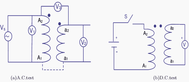
The transformer is connected to a low voltage a.c. source with the connections made as shown in the Figure 1 (a). A supply voltage Vs is applied to the primary and the readings of the voltmeters V1, V2 and V3 are noted. V1 : V2 gives the turns ratio.
If V3 reads V1−V2 then assumed dot locations are correct (for the connection shown).

Figure 1 - Transformer polarity test scheme
The beginning and end of the primary and secondary may then be marked by A1 − A2 and a1 − a2 respectively. If the voltage rises from A1 to A2 in the primary, at any instant it does so from a1 to a2 in the secondary.
If more secondary terminals are present due to taps taken from the windings they can be labeled as a3, a4, a5, a6. It is the voltage rising from smaller number towards larger ones in each winding. The same thing holds good if more secondaries are present.
Figure 1 (b) shows the d.c. method of testing the polarity. When the switch S is closed if the secondary voltage shows a positive reading, with a moving coil meter, the assumed polarity is correct. If the meter kicks back the assumed polarity is wrong.
Reference: Electrical Machines I – Prof. Krishna Vasudevan, Prof. G. Sridhara Rao, Prof. P. Sasidhara Rao